


| Quantity: | |
|---|---|


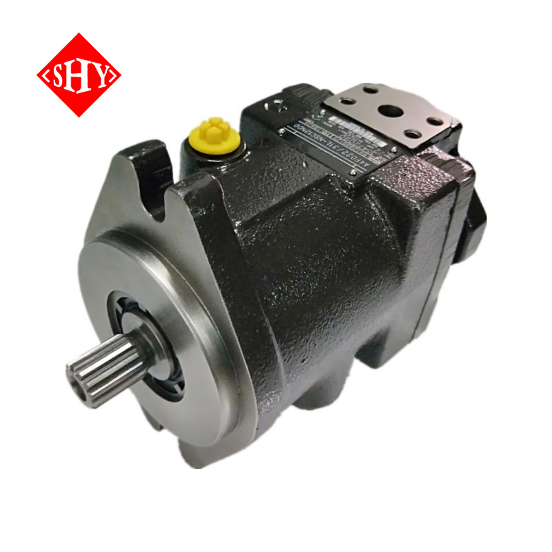
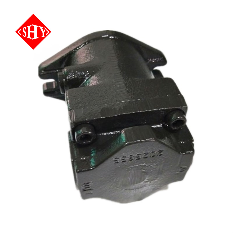
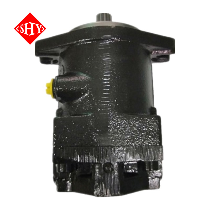
| A4FO Series A4FO22 A4FO28 A4FO40 A4FO71 A4FO125 A4FO180 A4FO250 A4FO500 Hydraulic Axial Piston Fixed Displacement Pump | ||||
| Data sheet | ||||
| Size | 16 to 500 | |||
| Series | 1 and 3 | |||
| Nominal pressure up | 400 bar | |||
| Peak pressure up | 450 bar | |||
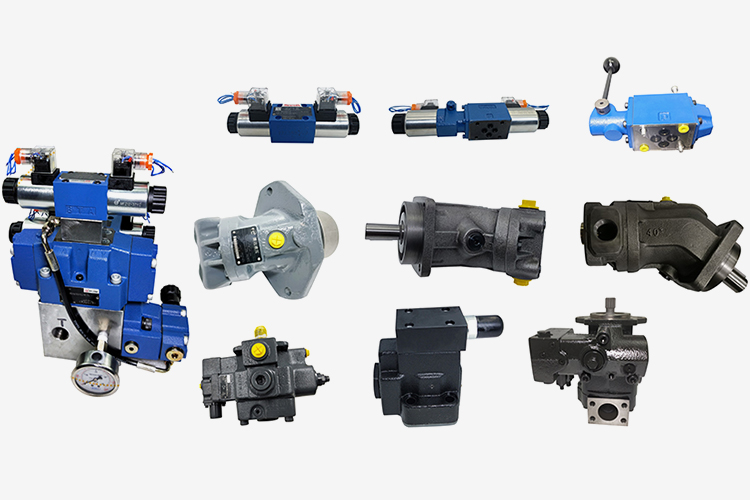
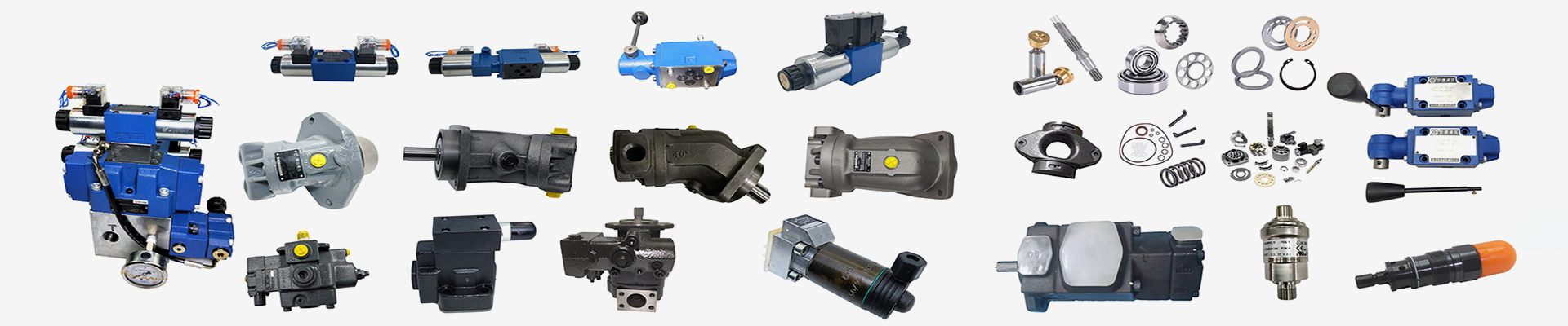
| Features | ||||
| – A4FO axial piston fixed displacement pumps of swashplate design are used for hydraulic drives in open loop circuits. | ||||
| – Flow is proportional to the drive speed and to the displacement. | ||||
| – Good suction characteristic | ||||
| – Low noise leve | ||||
| – Long service life | ||||
| – Pump combinations possible | ||||
| – Through drive for mounting other pumps | ||||
Table of values (theoretical values, without considering hmh and hv: values rounded)
Size | 16 | 22 | 28 | 40 | 71 | 125 | 250/H* | 500/H* | ||
Displacement | Vg | cm3 | 16 | 22 | 28 | 40 | 71 | 125 | 250 | 500 |
Max. speed | nmax | rpm | 4000 | 3600 | 3000 | 2750 | 2200 | 1800 | 1500 / 1900 | 1320 / 1500 |
Max. permissible speed (speed limit) with increased inlet pressure | nmax perm. | rpm | 4800 | 4500 | 3750 | 3400 | 2700 | 2200 | 1800 / 2100 | 1600 / 1800 |
Output flow at nmax | qV max | L/min | 62 | 77 | 81 | 107 | 152 | 218 | 364 / 461 | 640 / 728 |
Power at qV max; Dp = 400 bar | Pmax | kW | 43 | 53 | 56 | 73 | 91 | 131 | 219 / 277 | 385 / 437 |
Max. torque at Dp = 400 bar | Tmax | Nm | 102 | 140 | 178 | 254 | 395 | 696 | 1391 | 2783 |
Case volume | L | 0,3 | 0,3 | 0,3 | 0,4 | 2,0 | 3,0 | 7,0 | 11,0 | |
Moment of inertia, about drive axis | J | kgm2 | 0,0017 | 0,0017 | 0,0017 | 0,0030 | 0,0121 | 0,0300 | 0,0959 | 0,3325 |
Weight (approx.) | m | kg | 13,5 | 13,5 | 13,5 | 16,5 | 34 | 61 | 120 | 220 |
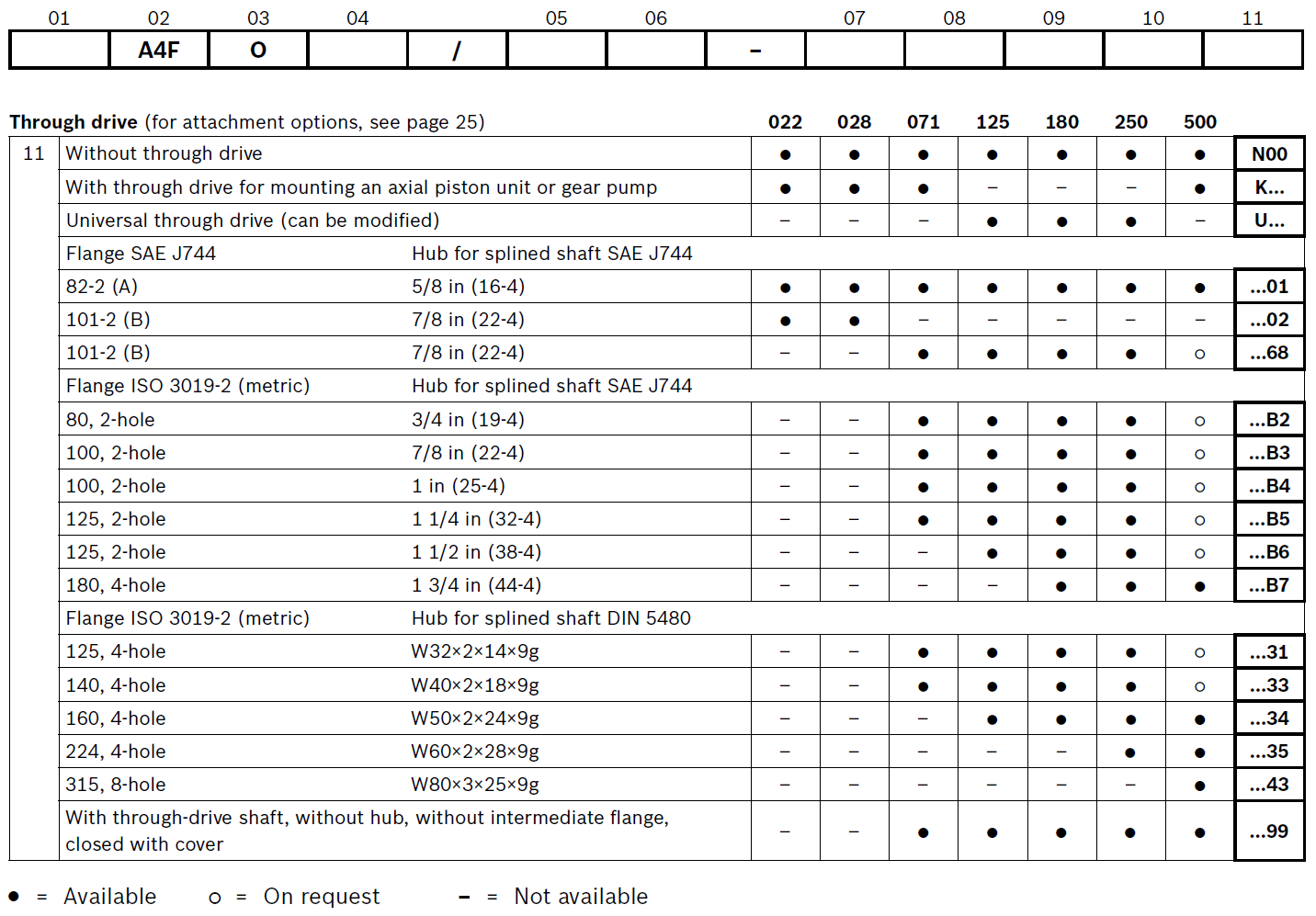
Ordering code for standard program:
99:With through-drive shaft, without hub, without intermediate flange,closed with cover


| A4FO Series A4FO22 A4FO28 A4FO40 A4FO71 A4FO125 A4FO180 A4FO250 A4FO500 Hydraulic Axial Piston Fixed Displacement Pump | ||||
| Data sheet | ||||
| Size | 16 to 500 | |||
| Series | 1 and 3 | |||
| Nominal pressure up | 400 bar | |||
| Peak pressure up | 450 bar | |||
| Features | ||||
| – A4FO axial piston fixed displacement pumps of swashplate design are used for hydraulic drives in open loop circuits. | ||||
| – Flow is proportional to the drive speed and to the displacement. | ||||
| – Good suction characteristic | ||||
| – Low noise leve | ||||
| – Long service life | ||||
| – Pump combinations possible | ||||
| – Through drive for mounting other pumps | ||||
Table of values (theoretical values, without considering hmh and hv: values rounded)
Size | 16 | 22 | 28 | 40 | 71 | 125 | 250/H* | 500/H* | ||
Displacement | Vg | cm3 | 16 | 22 | 28 | 40 | 71 | 125 | 250 | 500 |
Max. speed | nmax | rpm | 4000 | 3600 | 3000 | 2750 | 2200 | 1800 | 1500 / 1900 | 1320 / 1500 |
Max. permissible speed (speed limit) with increased inlet pressure | nmax perm. | rpm | 4800 | 4500 | 3750 | 3400 | 2700 | 2200 | 1800 / 2100 | 1600 / 1800 |
Output flow at nmax | qV max | L/min | 62 | 77 | 81 | 107 | 152 | 218 | 364 / 461 | 640 / 728 |
Power at qV max; Dp = 400 bar | Pmax | kW | 43 | 53 | 56 | 73 | 91 | 131 | 219 / 277 | 385 / 437 |
Max. torque at Dp = 400 bar | Tmax | Nm | 102 | 140 | 178 | 254 | 395 | 696 | 1391 | 2783 |
Case volume | L | 0,3 | 0,3 | 0,3 | 0,4 | 2,0 | 3,0 | 7,0 | 11,0 | |
Moment of inertia, about drive axis | J | kgm2 | 0,0017 | 0,0017 | 0,0017 | 0,0030 | 0,0121 | 0,0300 | 0,0959 | 0,3325 |
Weight (approx.) | m | kg | 13,5 | 13,5 | 13,5 | 16,5 | 34 | 61 | 120 | 220 |
Ordering code for standard program:
99:With through-drive shaft, without hub, without intermediate flange,closed with cover