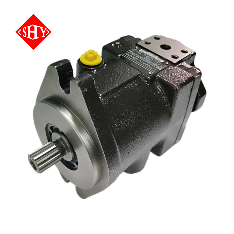
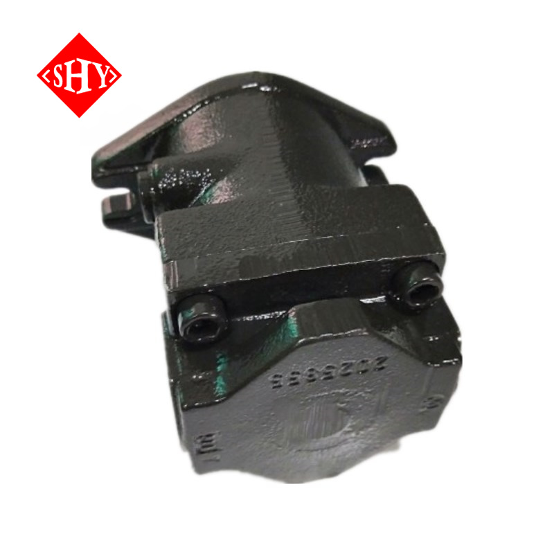
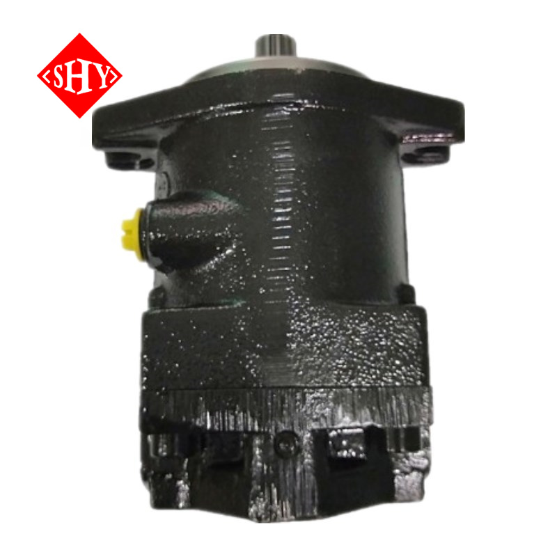
A4FO Series A4FO22 A4FO28 A4FO40 A4FO71 A4FO125 A4FO180 A4FO250 A4FO500 Hydraulic Axial Piston Fixed Displacement Pump
|
| Data sheet |
| Size | 16 to 500 |
| Series | 1 and 3 |
| Nominal pressure up | 400 bar |
| Peak pressure up | 450 bar |
| Features |
| – A4FO axial piston fixed displacement pumps of swashplate design are used for hydraulic drives in open loop circuits. |
| – Flow is proportional to the drive speed and to the displacement. |
| – Good suction characteristic |
| – Low noise leve |
| – Long service life |
| – Pump combinations possible |
| – Through drive for mounting other pumps |
Table of values (theoretical values, without considering hmh and hv: values rounded)
Size | 16 | 22 | 28 | 40 | 71 | 125 | 250/H* | 500/H* |
Displacement | Vg | cm3 | 16 | 22 | 28 | 40 | 71 | 125 | 250 | 500 |
Max. speed | nmax | rpm | 4000 | 3600 | 3000 | 2750 | 2200 | 1800 | 1500 / 1900 | 1320 / 1500 |
Max. permissible speed (speed limit) with increased inlet pressure | nmax perm. | rpm | 4800 | 4500 | 3750 | 3400 | 2700 | 2200 | 1800 / 2100 | 1600 / 1800 |
Output flow at nmax | qV max | L/min | 62 | 77 | 81 | 107 | 152 | 218 | 364 / 461 | 640 / 728 |
Power at qV max; Dp = 400 bar | Pmax | kW | 43 | 53 | 56 | 73 | 91 | 131 | 219 / 277 | 385 / 437 |
Max. torque at Dp = 400 bar | Tmax | Nm | 102 | 140 | 178 | 254 | 395 | 696 | 1391 | 2783 |
Case volume |
| L | 0,3 | 0,3 | 0,3 | 0,4 | 2,0 | 3,0 | 7,0 | 11,0 |
Moment of inertia, about drive axis | J | kgm2 | 0,0017 | 0,0017 | 0,0017 | 0,0030 | 0,0121 | 0,0300 | 0,0959 | 0,3325 |
Weight (approx.) | m | kg | 13,5 | 13,5 | 13,5 | 16,5 | 34 | 61 | 120 | 220 |
Ordering code for standard program:
E- or H-:
E-:HFA-, HFB-, HFC-Fluid
H-:High-Speed Design
A4FO: Series Number
016 or 022 or 028 or 040 or 071 or 125 or 180 or 250 or 500:Displacement Vg (cm3)
10 or 30 or 32: Series
10:A4FO 16、A4FO 22 、A4FO 28、A4FO 40
30:A4FO 71
32:A4FO 125、A4FO 180、A4FO 250、A4FO 500
R or L: viewed on shaft end :R:clockwise;L:anti-clockwise
N or P or V: Seals
N:NBR (nitril-caoutchouc), shaft seal in FKM (fluor-caoutchouc):A4FO 16、A4FO 22 、A4FO 28
P:NBR (nitril-caoutchouc), shaft seal in FKM (fluor-caoutchouc):A4FO 71、A4FO 125、A4FO 180、A4FO 250、A4FO 500
V:FKM (fluor-caoutchouc):A4FO 71、A4FO 125、A4FO 180、A4FO 250、A4FO 500
S or T or Z or P:
S:splined shaft SAE:A4FO 16、A4FO 22 、A4FO 28
T:splined shaft SAE:A4FO 40
Z:Splined shaft DIN 5480:A4FO 71、A4FO 125、A4FO 180、A4FO 250、A4FO 500
P:parallel shaft, with key DIN 6885:A4FO 71、A4FO 125、A4FO 180、A4FO 250、A4FO 500
C or B or H: Mounting flange
C:SAE 2-hole:A4FO 16、A4FO 22 、A4FO 28、A4FO 40
B:ISO 4-hole:A4FO 71、A4FO 125、A4FO 180、A4FO 250
H:ISO 8-hole:A4FO 500
12 or 25: Service line connections
12:Pressure and suction port SAE at side (opposite side) (metric fixing screws):A4FO 16、A4FO 22 、A4FO 28、A4FO 40
25:Pressure and suction port SAE at side, rotated by 90° (metric fixing screws) 2nd pressure port B1 opposite B - when delivered plugged with a flange:A4FO 71、A4FO 125、A4FO 180、A4FO 250、A4FO 500
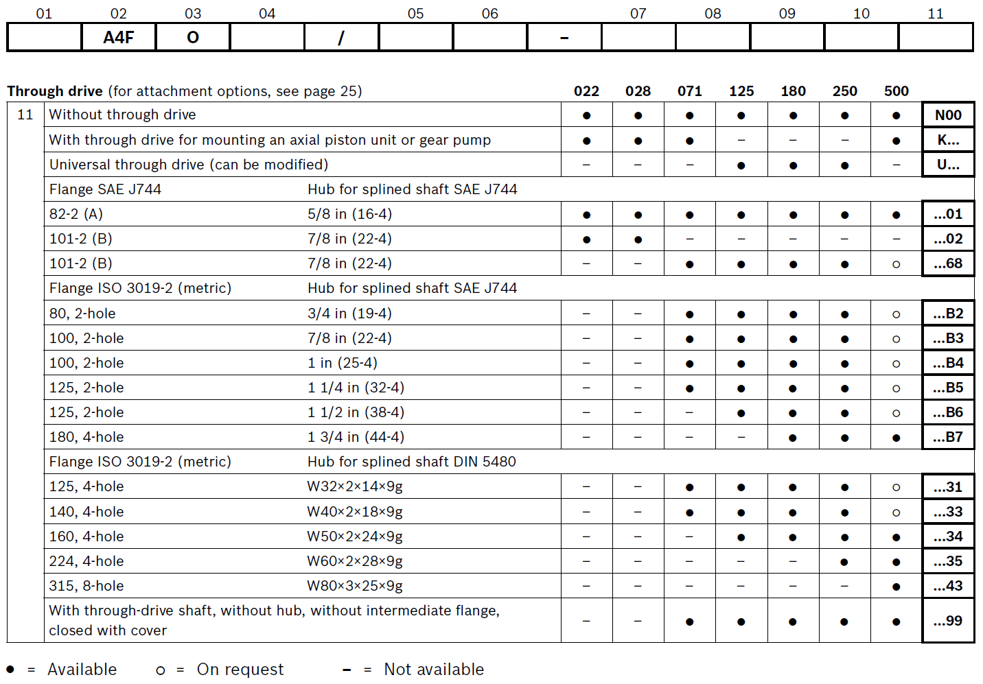
N00 or K or U: Through drive
N00:Without through drive
K:With through drive for mounting an axial piston unit or gear pump
U:Universal through drive (can be modified)
01 or 02 or 68:
01:Flange SAE J744:82-2(A);Hub for splined shaft SAE J744:5/8 in(16-4)
02:Flange SAE J744:101-2(B);Hub for splined shaft SAE J744:7/8 in (22-4)
68:Flange SAE J744:101-2(B);Hub for splined shaft SAE J744:7/8 in (22-4)
B2 or B3 or B4 or B5 or B6 or B7:
B2:Flange ls0 3019-2(metric):80, 2-hole;Hub for splined shaft SAE J744:3/4 in (19-4)
B3:Flange ls0 3019-2(metric):100, 2-hole;Hub for splined shaft SAE J744:7/8 in (22-4)
B4:Flange ls0 3019-2(metric):100, 2-hole;Hub for splined shaft SAE J744:1 in (25-4)
B5:Flange ls0 3019-2(metric):125, 2-hole;Hub for splined shaft SAE J744:1 1/4 in (32-4)
B6:Flange ls0 3019-2(metric):125, 2-hole;Hub for splined shaft SAE J744:1 1/2 in (38-4)
B7:Flange ls0 3019-2(metric):180, 4-hole;Hub for splined shaft SAE J744:1 3/4 in (44-4)
31 or 33 or 34 or 35 or 43 or 99:
31:Flange ls0 3019-2 (metric):125, 4-hole;Hub for splined shaft DlN 5480:W32x2x14x9g
33:Flange ls0 3019-2 (metric):140.4-hole;Hub for splined shaft DlN 5480:W40x2x18x9g
34:Flange ls0 3019-2 (metric):160, 4-hole;Hub for splined shaft DlN 5480:W50x2x24x9g
35:Flange ls0 3019-2 (metric):224, 4-hole;Hub for splined shaft DlN 5480:W60x2x28x9g
43:Flange ls0 3019-2 (metric):315, 8-hole;Hub for splined shaft DlN 5480:W80x3x25x9g
99:With through-drive shaft, without hub, without intermediate flange,closed with cover
A complete model, for example:A4FO-71/10R-PPB25N00