


Views: 0 Author: Site Editor Publish Time: 2026-09-15 Origin: Site


A fundamental rule of fluid power governs every hydraulic system: pumps do not generate pressure; they generate flow. Pressure is the strict result of resistance to that flow. When fluid encounters a restriction—whether from a heavy load, a narrow valve, or cylinder friction—hydrostatic pressure builds. A piston pump provides the mechanical force necessary to push fluid against this resistance without failing. Specifying a hydraulic system without a precise understanding of how different pump architectures handle flow, resistance, and internal tolerances leads to severe consequences. Engineers often face catastrophic system failures, rapid cavitation, or over-specified components. You must match the pump's mechanical capabilities to the exact load profile it will encounter. We outline the shift from basic mechanical principles to advanced specification criteria. This establishes a clear framework for evaluating which pump architecture aligns with specific industrial or mobile load profiles.
Mechanism Reality: A piston pump generates flow via reciprocating motion; system pressure is dictated by the load resistance and the pump's structural threshold.
Architecture Matters: Axial (swashplate and bent-axis) and radial designs offer distinct trade-offs between maximum pressure thresholds, footprint, and flow rates.
Displacement Control: Variable displacement models allow for dynamic pressure and flow adjustment, directly impacting energy efficiency, prime mover sizing, and thermal management.
Circuit Compatibility: Open and closed-circuit systems require specific pump configurations to manage inlet conditions, filtration, and prevent cavitation.
Piston pumps rely on a straightforward mechanical sequence to move fluid. The drive shaft turns the cylinder barrel, which houses multiple pistons inside precisely machined bores. As the barrel rotates, the piston shoes slide along an angled swashplate. This interaction creates a continuous cycle of suction and discharge.
Suction Phase: The swashplate angle pulls the piston out of the bore, increasing the internal volume. This volume increase drops the internal pressure below atmospheric levels. Fluid from the reservoir rushes in to fill the void.
Transition Phase: The barrel rotates the fluid-filled bore past the suction port and seals it momentarily against the valve plate.
Displacement Phase: The swashplate pushes the piston back into the bore. The internal volume decreases rapidly, forcing the trapped fluid out through the discharge port and into the hydraulic circuit.
Unlike gear pumps that rely on meshing teeth with relatively large clearances, piston designs use incredibly tight tolerances between the piston and the bore. We are talking about clearances of just a few microns. This precision gives them massive volumetric efficiency. Even when pushing against extreme resistance, the fluid cannot easily slip backward. It has to go out the discharge port.
Mechanics often hook up a gauge, see zero pressure, and assume the pump is dead. But if the fluid is just dumping back to the tank through an open directional valve, there is no resistance. The pump might be moving 50 gallons per minute, but the gauge reads zero. A pump displaces a specific, fixed volume of fluid per revolution. It does not create pressure directly.
Pressure only happens when you block that flow. Imagine a hydraulic cylinder trying to lift a 20-ton steel beam. The fluid enters the cylinder and hits the piston face. The 20-ton weight pushes back. The fluid cannot move forward until it overcomes that 20-ton resistance. The pump keeps forcing more fluid into the line. The fluid compresses slightly, and hydrostatic pressure spikes. The pressure will keep climbing until it generates enough force to lift the beam, or until a relief valve opens. The pump does not decide the pressure; the 20-ton beam does.
To make this continuous flow work, you have to separate the suction side from the discharge side. Radial designs use heavy-duty mechanical check valves. A spring holds a poppet shut. Suction vacuum pulls it open; discharge force slams it shut. Axial designs use a stationary valve plate. The rotating barrel spins against this bronze or steel plate. The plate has two kidney-shaped slots: one connected to the inlet, one to the outlet. As the barrel spins, each piston bore passes over the suction kidney, fills with oil, and then passes over the discharge kidney to push the oil out.
Because you have a specific number of pistons, usually an odd number like 7 or 9, the flow is not perfectly smooth. You get a slight surge every time a piston transitions from suction to discharge. We call this a pressure ripple. If you do not manage these ripples with proper hose routing and accumulators, they will vibrate steel hardlines until the fittings crack and leak. Engineers mitigate this by machining pre-compression grooves into the valve plate to smooth the pressure transitions before the bore fully opens to the discharge port.
Axial pumps align the pistons parallel to the main drive shaft. You will see two main variations in the field: inline swashplate and bent-axis.
In an inline swashplate design, the drive shaft, cylinder barrel, and pistons all sit in a straight line. The pistons stroke back and forth because their shoes ride on an angled swashplate. This layout is highly responsive. You can change the swashplate angle quickly to adjust flow. However, the angled push creates a side-load on the pistons. They rub hard against the side of the cylinder bore. This side-loading limits the maximum pressure they can handle before wear becomes excessive.
Bent-axis designs solve the side-loading problem. The swashplate is gone. Instead, the entire cylinder barrel sits at an angle to the drive shaft. A heavy-duty universal joint or tapered gear connects them. Because the pistons move perfectly in line with the bore, side-loading drops to almost zero. This allows bent-axis models to spin much faster and handle higher pressures than inline versions. You will find bent-axis units on heavy-duty winches and continuous high-speed drives.
Radial pumps look completely different. The pistons sit perpendicular to the drive shaft, radiating outward like spokes on a wheel. The drive shaft has an eccentric cam in the middle. As the shaft spins, the cam pushes the pistons outward. Heavy coil springs push them back inward.
This geometry is built for brute force. The mechanical loads transfer directly into a massive central shaft and a thick cast-iron outer housing. There is no delicate swashplate to bend. When you need to hold 600 bar of pressure on a massive metal-forming press for hours at a time, you use a radial pump. They do not spin fast, and they do not move massive volumes of oil, but they will hold extreme pressure without destroying themselves.
You cannot just grab any pump off the shelf. You have to match the internal architecture to what the machine actually does. Evaluate the duty cycle, peak pressure spikes, spatial constraints, and required lifespan under maximum load.
Architecture Type | Maximum Pressure Range | Speed Capability | Ideal Load Profile | Primary Limitation |
|---|---|---|---|---|
Axial Swashplate | Up to 350 - 400 bar | High | Variable flow demands, mobile equipment, compact spaces. | Piston side-loading limits extreme pressure durability. |
Axial Bent-Axis | Up to 400 - 450 bar | Very High | Continuous high-speed operation, heavy-duty winches, drives. | Larger physical envelope than inline swashplate designs. |
Radial Piston | 600+ bar | Low to Moderate | Sustained ultra-high pressure, clamping, metal forming. | Lower maximum flow rates, heavy, bulky footprint. |
In an open circuit, the pump pulls oil out of a large atmospheric reservoir. It pushes the oil through the control valves, into the cylinders, and then the oil dumps back into the reservoir. The oil gets a chance to rest. Air bubbles rise to the surface, and heat dissipates through the steel tank walls.
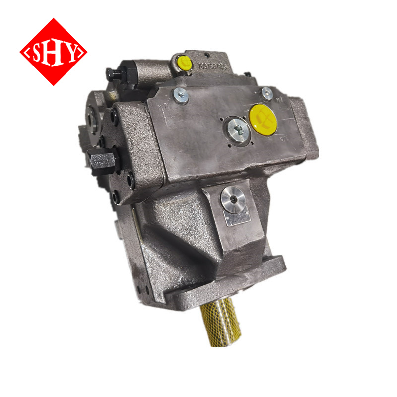
You have plenty of room to install massive return-line filters and water-cooled heat exchangers. The main challenge is getting the oil into the pump. The pump relies entirely on atmospheric pressure to push oil up the suction hose. If that hose is too long, too narrow, or has too many 90-degree elbows, the pump will starve. For heavy industrial setups where you need massive flow from a tank, we specify units like the A4VSO40-355 hydraulic piston pump. It handles continuous high-pressure demands while drawing effectively from open reservoirs.
Closed circuits do not use a main reservoir for the working fluid. The pump pushes oil directly into a hydraulic motor. The oil leaving the motor goes straight back into the pump inlet. It is a continuous, closed loop. We use this almost exclusively for hydrostatic transmissions on mobile equipment like excavators and skid steers.
Because the loop is closed, any oil that leaks past the internal clearances is lost from the loop. If you lose oil, you lose pressure. To fix this, closed-circuit pumps have a small, built-in charge pump. This charge pump pulls a small amount of oil from a secondary tank and injects it into the low-pressure side of the loop. It replaces the lost oil and keeps the loop pressurized. The A4VG45/85/110/280 closed-circuit piston pump includes the charge pump and cross-port relief valves right in the housing to handle the massive pressure spikes that happen when a heavy machine suddenly changes direction.
A fixed displacement pump has a set stroke length. If it displaces 50cc per revolution, and you spin it at 1500 RPM, it will output exactly 75 liters per minute. It does not care if the machine needs 75 liters or 5 liters. It just keeps pumping.
When a hydraulic cylinder hits the end of its stroke, the fluid has nowhere to go. Pressure spikes instantly. To keep the pump from exploding, you have to install a main relief valve. The relief valve pops open and dumps all 75 liters per minute back to the tank at maximum system pressure. Forcing high-pressure oil through a tiny relief valve orifice generates massive amounts of heat. You burn diesel fuel just to boil your hydraulic oil.
Variable displacement fixes this massive energy waste. Instead of a fixed swashplate, the swashplate sits on trunnion bearings. A small hydraulic control piston can tilt the swashplate back and forth while the pump is spinning.
If you tilt the swashplate to a steep angle, the pistons take a long stroke. You get maximum flow. If you flatten the swashplate out to zero degrees, the pistons stop stroking entirely. The barrel still spins, but no oil moves. You change the flow output without changing the engine RPM. The A11V(L)O40-260 high-pressure axial pump uses this mechanism to adapt to changing loads instantly. It gives you high flow when you need speed, and low flow when you just need to hold pressure.
You control that swashplate angle using advanced hydraulic compensators bolted to the side of the pump. These controls automate the pump's response to system resistance.
Pressure Compensation: This acts as an automatic safety valve. You set it to your maximum desired pressure, say 300 bar. The pump delivers full flow until the system hits 300 bar. The moment it hits 300 bar, the compensator sends a pressure signal to the control piston. The piston flattens the swashplate. The pump stops producing flow, but it maintains exactly 300 bar of holding pressure.
Load Sensing: A small hydraulic line runs from the directional valve back to the pump. It tells the pump exactly how much pressure the load requires right now. If the load only needs 100 bar, the pump only generates 100 bar plus a small 20 bar standby margin. It matches flow and pressure perfectly to the demand.
Torque Limiting: Hydraulic horsepower is flow multiplied by pressure. If you demand maximum flow and maximum pressure at the same time, you will stall the diesel engine. The torque limiter monitors the pressure. As pressure climbs, it automatically reduces the swashplate angle to cut the flow. This keeps the total horsepower demand just below the engine's stall point.
The fastest way to destroy a piston pump is to starve the inlet. If the suction line is too small, or the suction filter is clogged, the pump tries to pull oil that isn't there. The absolute pressure inside the piston bore drops so low that the hydraulic oil literally boils at room temperature.
This boiling creates thousands of tiny vapor cavities. As the barrel rotates, these vapor bubbles move from the low-pressure suction side to the high-pressure discharge side. The sudden spike in pressure causes the bubbles to implode violently. These micro-implosions act like tiny shaped charges. They blast microscopic chunks of metal out of the brass valve plate and the steel piston shoes. The pump will sound like it is pumping marbles, and it will tear itself apart in hours. You prevent this by using oversized suction lines, keeping the reservoir oil level above the pump inlet, and eliminating unnecessary elbows in the plumbing.
When you generate 350 bar of pressure, the oil wants to escape. A tiny amount of oil constantly squeezes past the piston rings and the valve plate, leaking back into the pump casing. We call this internal leakage slip. You actually need a little bit of slip to lubricate the internal bearings and carry away heat.
But as that high-pressure oil forces its way through microscopic gaps, fluid friction creates intense heat. If the oil gets too hot, its viscosity drops. It gets thin like water. Thin oil slips even faster, which creates even more heat. It is a death spiral. Once the oil gets too thin, the protective fluid film between the piston shoe and the swashplate collapses. You get metal-on-metal contact, and the pump fails. You must install properly sized air-to-oil or water-to-oil heat exchangers to keep the fluid viscosity stable.
You cannot run dirty oil through a high-pressure system. The clearances between the piston and the bore are often less than 10 microns. A single grain of talcum powder is about 10 microns.
If silica dust from the job site or metal shavings from a worn cylinder get into the oil, they act like lapping compound. As the pump forces these particles through the tight clearances at high pressure, they score deep scratches into the valve plate and the cylinder bores. Once those surfaces are scratched, high-pressure oil easily bypasses the discharge port and leaks back into the case. The pump loses its volumetric efficiency. You will notice the machine slowing down when it tries to lift a heavy load. You must use high-efficiency glass-fiber filters and maintain strict ISO cleanliness codes, like ISO 4406 18/16/13, to keep the pump alive.
Audit your current system's maximum flow requirements and calculate the peak load resistance to establish a baseline pressure threshold.
Inspect your suction lines and reservoir elevation to guarantee positive inlet pressure and eliminate cavitation risks.
Implement a rigorous fluid analysis program to verify your oil meets the strict ISO cleanliness standards required by piston tolerances.
Consult technical data sheets for specific variable displacement controls to optimize energy efficiency and reduce thermal loads.
A: Maximum pressure depends heavily on the architectural design. Axial piston pumps typically handle continuous pressures up to 350 or 400 bar. Radial piston pumps, due to their robust perpendicular geometry, can sustain extreme pressures exceeding 600 bar for specialized industrial applications.
A: Pressure loss under load usually indicates excessive internal leakage, known as slip. This occurs when particulate contamination scores the valve plate or piston bores, widening the microscopic clearances. The fluid bypasses the discharge port and leaks back into the pump casing, reducing volumetric efficiency.
A: Flow is the volume of fluid moved by the pump per minute, which determines actuator speed. Pressure is the resistance to that flow, generated by the load weight or line restrictions. The pump creates flow; the system's resistance creates pressure.
A: The swashplate angle dictates the piston stroke length, controlling flow output. While it does not directly set system pressure, altering the angle via a pressure compensator allows the pump to reduce flow to zero when a maximum pressure threshold is reached, maintaining pressure without stalling the motor.
A: Cavitation occurs when inlet fluid supply is restricted, causing absolute pressure to drop and vapor bubbles to form. When these bubbles enter the high-pressure discharge zone, they implode violently. This destroys internal components, rapidly degrading the pump's ability to maintain high pressure.
A: Piston pumps rely on clearances smaller than 10 microns to seal high-pressure fluid. Contaminants act as abrasives, scratching the pistons and valve plates. This wear increases internal leakage, preventing the pump from pushing fluid against heavy resistance, resulting in pressure loss.


