


Views: 0 Author: Site Editor Publish Time: 2026-06-02 Origin: Site


Specifying the wrong hydraulic motor carries incredibly high stakes. Premature component failure, drastic system inefficiency, and unplanned machine downtime can easily cripple entire production lines. You simply cannot afford to guess when making this critical engineering choice.
The choice between a vane design and a gear design is never about finding a universally "good" or "bad" option. Instead, you must strictly align component physics with specific application demands. Operating pressure, fluid cleanliness, and acoustic limits completely govern this decision. Ignoring these technical realities leads to catastrophic failure and wasted operational resources.
This guide will thoroughly dismantle the performance, maintenance, and lifecycle realities of both motor types. We will provide a clear, engineering-led framework to guide your selection process. You will learn exactly how to match the right motor technology directly to your specific operational needs.
Vane Motors excel in medium-pressure applications requiring low noise, high efficiency at lower speeds, and smooth rotation.
Gear Motors are the undisputed choice for rugged environments, offering high tolerance for fluid contamination and low initial cost.
System scalability dictates motor type: fixed displacement applications lean toward gear or simple vane types, while systems requiring adaptive flow control may necessitate a hydraulic variable vane motor.
You cannot select the proper component without first understanding the internal physics. Each design converts hydraulic fluid pressure into rotational mechanical force using entirely different mechanical pathways. These distinct physical approaches dictate how they perform under stress.
The internal mechanism relies on a slotted rotor housed inside a cam ring. The rotor sits eccentrically within this ring. When you start the system, centrifugal force throws internal flat metal vanes outward from the rotor slots. High-pressure hydraulic fluid then channels underneath these vanes. This fluid pressure securely locks the vanes against the inner surface of the cam ring. The changing internal volume forces the entire rotor assembly to turn smoothly.
This approach features a brilliant self-compensating wear design. Over thousands of operational hours, the tips of the vanes naturally grind down. However, centrifugal force and underlying fluid pressure simply push the worn vanes further outward. They continuously maintain physical contact. This ensures volumetric efficiency remains highly stable over a very long operational lifespan.
You must acknowledge one strict limitation. These complex internal parts show extreme susceptibility to shear degradation. If you introduce highly contaminated fluid, debris quickly damages the delicate sliding surfaces.
Best Practices for Vane Units:
Always prime the system thoroughly before the initial startup sequence.
Ensure your fluid achieves operating temperature quickly to maintain proper viscosity.
Never operate the unit below the manufacturer's recommended minimum rotational speed.
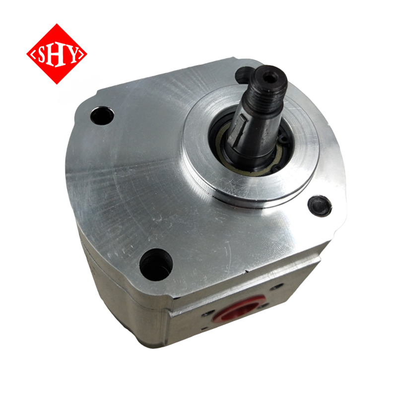
The operational mechanism here is brilliantly simple. Two gears mesh tightly together inside a rigid housing. One gear connects directly to the output shaft. Fluid enters the inlet port and flows around the outer periphery of the gear teeth. The meshing action blocks fluid from passing directly between the gears. This fluid pressure unbalances the gears, forcing them to rotate rapidly toward the outlet port.
This design offers exceptional mechanical ruggedness. It lacks delicate sliding components. You get an incredibly robust power source capable of shrugging off moderate physical abuse.
We must frame the primary trade-off clearly. These units tolerate dirty environments easily. However, intense metal-on-metal friction eventually wears down the gear teeth and the internal housing walls. This wear creates larger internal clearances. Hydraulic fluid begins slipping through these widened gaps. This internal leakage permanently drops the unit's volumetric efficiency over time.
Engineers evaluate hydraulic performance across three critical metrics. You must measure volumetric efficiency, acoustic emissions, and pressure limitations carefully.
You will notice distinct performance curves when testing speed stability. Gear mechanisms deliver exceptional efficiency at high rotational speeds. They move large fluid volumes rapidly. However, they struggle severely at low speeds. The meshing gear teeth cause noticeable pulsation. This creates a jerky, inconsistent output shaft rotation known as cogging.
Vane designs behave oppositely. They provide incredibly smooth output rotation at very low speeds. The continuous sliding action eliminates low-speed cogging entirely. This makes them ideal for precision tooling and delicate material handling operations.
Modern applications often require adaptive flow control. A hydraulic variable vane motor provides a massive critical advantage here. When your machinery faces rapidly fluctuating torque and speed requirements, this unit adapts its internal displacement automatically. You achieve precise system tuning continuously. You completely eliminate the parasitic energy losses associated with dumping excess fluid over a relief valve.
Industrial noise pollution represents a major safety concern. Fluid trapping between gear teeth creates intense pressure spikes. These spikes generate loud, high-frequency acoustic noise. You will hear a distinct whining sound in gear-driven systems.
The empirical reality favors continuous flow designs. A Rotary vane motor operates significantly quieter. The fluid transfers smoothly without sudden compression spikes. You should position vane units as the mandatory choice for indoor manufacturing environments. They help you meet strict OSHA noise compliance limits easily. You avoid purchasing expensive acoustic dampening enclosures.
Standard operating pressure envelopes dictate your component options. Piston units absolutely dominate the extreme high-pressure tier above 350 bar. However, gear and vane designs compete fiercely in the medium-pressure tier.
Both technologies operate comfortably up to 250-300 bar, depending on exact manufacturer specifications. You must evaluate the starting torque requirements carefully. Vane units often require higher initial pressure to break internal static friction and extend the vanes effectively.
Performance Metric | Vane Design | Gear Design |
|---|---|---|
Low-Speed Smoothness | Excellent (No cogging) | Poor (Prone to jerking) |
Acoustic Emissions | Very Low (Quiet operation) | High (Significant whining) |
Volumetric Efficiency Drop | Minimal (Self-compensating) | Continuous (As housing wears) |
High-Speed Efficiency | Moderate to Good | Excellent |
You cannot evaluate hydraulic hardware without discussing fluid management. Fluid quality directly determines component survival rates in the field.
We must establish fluid contamination as the primary cause of sudden hydraulic failure. Microscopic dirt, abrasive metal shavings, and trapped moisture destroy internal surfaces rapidly. You must treat hydraulic fluid as a delicate structural component.
We choose gear units for rugged tasks because they tolerate particulate matter better. Their internal clearances are inherently larger. Their physical parts carry massive structural bulk. A stray piece of metal might scratch a gear tooth heavily. It rarely stops the entire drive mechanism dead. They power through moderate debris loads successfully.
Detailing the risk for vane mechanisms is crucial. A tiny particulate can enter the narrow rotor slots. This debris jams the sliding vanes tightly in place. Centrifugal force cannot push the jammed vane outward. Fluid immediately bypasses the rotor core entirely. This leads to catastrophic loss of rotational torque. You must maintain strict ISO fluid cleanliness codes constantly. You must install superior filtration circuits throughout the machine architecture.
Buyers often try to save budget capital quickly. They purchase a cheaper gear unit for a precision machine. They quickly discover their system requires smooth, low-speed operation. The cheap gear unit causes severe system vibrations. It damages connected mechanical linkages permanently. They spend more repairing the machine than they saved on the component.
Conversely, someone might install a highly precise Vane Motor on a mobile construction excavator. They completely fail to upgrade the surrounding filtration circuits. The dirty outdoor environment overwhelms the standard filters rapidly. Particulates flood the system. The motor fails immediately. You must match the technology exactly to the environmental reality.
Procurement teams often focus entirely on the initial purchase price. Engineers must look beyond the invoice and evaluate the complete lifecycle cost trajectory.
We readily acknowledge standard gear units carry a lower upfront procurement cost. Their straightforward manufacturing process requires fewer precision machining steps. This keeps basic unit prices highly attractive for bulk purchasing.
However, you must introduce high-tier gear options into your calculations. Not all gear units qualify as simple "budget" items. For incredibly heavy-duty applications, specifying an AZMB AZMF AZMN AZMG Hydraulic High Performance External Gear Motor changes the equation entirely. This component provides premium durability. It guarantees exact displacement matching under severe load. Heavy industrial operations easily justify this higher initial spend because it prevents catastrophic mid-cycle failures.
You must break down maintenance realities accurately. When internal parts eventually fail, repair procedures differ wildly.
Vane designs offer a massive maintenance advantage. They frequently utilize interchangeable "cartridge kits." The entire rotating internal group slides out as one unified piece. You remove four outer bolts. You slide the old cartridge out. You push the new cartridge in. You accomplish this inline rebuild without removing the heavy outer housing from the parent machine. You restore full functionality in under an hour.
Gear assemblies present a harsh contrast. Once the internal housing walls wear down, you cannot install a quick fix. You typically require a full unit replacement. You must disconnect rigid hydraulic lines. You must unbolt heavy mounting flanges. You must realign the output shafts carefully. Frame this reality correctly: complete replacement causes extended downtime. It halts production lines for hours or days. This impacts long-term profitability severely.
You need a rigid selection framework. Follow this specific engineering logic to protect your machinery.
You should select a gear design when operating conditions match these criteria:
The external environment remains harsh, dirty, or highly abrasive. Agricultural tractors and mobile forestry equipment fit perfectly here.
The project budget faces strict, unyielding capital caps.
Ambient acoustic noise does not present a safety or regulatory concern.
High-speed, low-torque operational cycles dominate the daily workload.
You should select a vane design when facing these specific operational demands:
The application exists entirely indoors. Plastic injection molding machines and industrial stamping presses are perfect candidates.
Low acoustic noise is absolutely critical for workplace safety compliance.
The machinery requires incredibly smooth start-up torque without sudden jerking movements.
The facility maintains strict fluid filtration protocols and regular oil analysis routines.
Do not guess your operational parameters. We urge you to audit your current hydraulic fluid ISO cleanliness rating immediately. Pull fluid samples from your active reservoir. Send them to a laboratory for exact particulate counting.
Next, map the exact torque curve your machinery requires across a full operational cycle. Determine your starting torque, running torque, and maximum speed accurately. Only after gathering this hard data should you request formal vendor quotes.
Neither hydraulic technology is universally superior. The absolute superiority of a vane or gear design depends entirely on your specific application matrix. Your fluid cleanliness levels, strict acoustic requirements, and operational duty cycle dictate the final answer.
We encourage you to consult directly with a certified hydraulic applications engineer before purchasing. Review detailed OEM specification sheets carefully. Evaluate your current filtration infrastructure thoroughly. Upgrading your filters often costs less than replacing blown hydraulic hardware. Make your procurement decisions based on verifiable engineering data, and your machinery will run efficiently for decades.
A: You must address specific mounting flange standards first. Industry standards like SAE mounts often match physically. However, you must verify your fluid filtration capabilities aggressively. You also need to check pressure drain line requirements before attempting any direct swap. Inadequate filtration will destroy the new unit.
A: Pressure loss typically stems from internal vane sticking. Varnish buildup or heavy particulate contamination jams the flat vanes inside their rotor slots. They fail to extend against the cam ring properly. This creates massive internal fluid leakage. It primarily represents a fluid cleanliness failure, completely dispelling the myth that the design itself is mechanically weak.
A: You can control their rotational speed using external flow control valves. However, they completely lack the inherent efficiency adaptability of a true variable displacement unit. They bleed off excess hydraulic flow as pure heat. This wastes tremendous energy. They are rarely optimal for highly dynamic variable speed applications.


