


Views: 0 Author: Site Editor Publish Time: 2026-08-18 Origin: Site


High-pressure, closed-circuit hydrostatic drives require variable axial piston pumps capable of sustaining continuous heavy-duty loads without compromising volumetric efficiency. Incorrectly specifying a pump's displacement, series, or control module leads to system overheating, inadequate torque transfer, premature component failure, and costly machine downtime. Selecting the exact hardware configuration determines whether a machine operates at peak hydraulic horsepower or suffers from chronic sluggishness under load. This guide provides a technical evaluation framework for selecting the correct pump, comparing pressure ratings across series, analyzing control methods, and mitigating implementation risks to ensure a seamless replacement. You will learn how to decode OEM specifications, match control modules to machine architecture, and execute commissioning protocols that protect the hydrostatic loop.
Series Distinction: Series 32 operates at 400 bar nominal (450 bar peak), while Series 40 is engineered for higher power density at 450 bar nominal (500 bar peak).
Control Versatility: Selection depends on system architecture; options range from basic mechanical (HW) and hydraulic direct control (HD) to advanced proportional electrical (EP) and speed-related (DA) controls.
Circuit Architecture: The A4VG is strictly for closed-circuit applications; open-circuit requirements necessitate alternative models like the A4VSO.
Identification: Exact replacement requires cross-referencing specific OEM part numbers (e.g., Rexroth R-numbers).
Implementation Focus: Long-term reliability requires strict adherence to fluid cleanliness standards, proper case drain routing, and accurate charge pump sizing.
Defining the baseline requirements for hydrostatic drives is the first step in the selection process. Engineers and maintenance professionals must evaluate the required flow rate, continuous operating pressure, and spatial constraints within the machine envelope. A pump that fits physically but fails to deliver the necessary flow at peak pressure will stall the drive motors during heavy operation. Success criteria depend on matching the pump's output curve directly to the load requirements of the transmission or rotary drive. When specifying an A4VG hydraulic pump, you must account for the prime mover's horsepower and the maximum torque required at the ground or the work tool.
The variable axial piston swashplate design dictates flow proportionality to drive speed and displacement. Inside the rotating group, pistons reciprocate within a cylinder block. The angle of the swashplate determines the stroke length of these pistons. When the swashplate rests at zero degrees, the pistons do not stroke. This results in zero flow despite the input shaft rotating at full engine RPM. As the control module angles the swashplate, the piston stroke increases. This action delivers proportional hydraulic flow to the closed circuit. This variable displacement capability allows for infinitely adjustable speed control of the connected hydraulic motors without altering the prime mover's engine speed. The mechanical integrity of the swashplate bearings and the control piston determines how smoothly the machine accelerates under load.
Integrated auxiliary components significantly reduce the need for external plumbing. This makes closed-circuit systems more compact and reliable. The built-in boost pump, commonly known as the charge pump, replenishes fluid lost to internal leakage. It maintains positive pressure in the low-pressure loop to prevent cavitation and supplies control pressure to the swashplate actuators. High-pressure relief valves protect the main loop from pressure spikes. Makeup valves allow charge oil to enter the low-pressure side of the circuit. These integrated features streamline installation but require careful sizing. You must ensure the charge pump can handle the volumetric demands of the specific application, especially if auxiliary functions draw from the same charge circuit. Standard charge pumps typically displace 10% to 25% of the main pump's maximum volume.
Matching exact OEM identification numbers found on the data plate guarantees compatibility with existing machine hydraulics. A visual match of the casting is never sufficient. The Rexroth R-number acts as the DNA of the pump. It dictates the exact displacement, rotation direction, shaft spline type, mounting flange, control module configuration, and relief valve settings. Installing a pump with a mismatched R-number can result in reversed drive directions, incompatible control signals, or immediate mechanical failure due to spline mismatch. Always clean the data plate and record the full alphanumeric sequence before ordering a replacement unit. Field technicians often encounter situations where a pump looks identical but features a left-hand rotation instead of a right-hand rotation, leading to catastrophic failure upon startup.
Comparing the two primary generations of this pump requires evaluating power density, footprint, maximum pressure thresholds, and integration requirements. As mobile machinery evolves to demand more power from smaller engine compartments, hydraulic components must deliver higher pressures without increasing physical dimensions. The transition from Series 32 to Series 40 represents a shift toward these high-density requirements. Upgrading a machine's hydraulic system often involves analyzing whether the existing plumbing and motors can handle the increased pressure capabilities of the newer series.
Specification | Series 32 | Series 40 |
|---|---|---|
Nominal Pressure | 400 bar | 450 bar |
Maximum Peak Pressure | 450 bar | 500 bar |
Displacement Range | 28cc to 250cc | 45cc to 280cc |
Power Density | Standard | High (Optimized footprint) |
Primary Application | Legacy replacements, medium-duty | Modern heavy-duty, high-torque |
The A4VG28/40/56/71/90/125/180/250 Series 32 hydraulic pump operates at a nominal pressure of 400 bar and withstands maximum peak pressures of 450 bar. This pressure rating covers a vast range of displacement sizes, from 28cc up to 250cc per revolution. The robust design utilizes proven rotary group geometry that has served as the industry standard for decades. The internal trunnion bearings and control pistons handle continuous duty cycles within this 400-bar threshold, providing stable flow characteristics across varying temperature ranges. The cylinder block and valve plate interface is engineered to maintain high volumetric efficiency even after thousands of hours of operation.
Applications for Series 32 are predominantly found in legacy equipment replacements, medium-duty construction machinery, and agricultural equipment. Harvesters, mid-sized wheel loaders, and standard asphalt pavers rely heavily on this series. Because these machines were originally designed around the 400-bar parameter, upgrading to a higher-pressure pump offers no operational benefit. It may actually introduce compatibility issues with existing hydraulic motors and hoses. The structural integrity of older machine frames and gearboxes is often matched specifically to the torque output generated at 400 bar.
Selecting Series 32 involves balancing proven reliability and widespread aftermarket parts availability against slightly lower power density compared to newer iterations. Maintenance teams often prefer this series because the rebuild procedures are universally understood. Seal kits, valve plates, and cylinder blocks are readily accessible globally. The slightly larger physical envelope rarely presents an issue in older machines where space constraints are less severe. Mechanics can easily access the control modules and charge pump housings for routine maintenance without removing the entire unit from the machine.
The A4VG45/65/85/110/145/175/210/280 Series 40 hydraulic pump represents a significant engineering upgrade. It features a nominal pressure rating of 450 bar and a maximum peak pressure of 500 bar. This expanded size range accommodates higher torque requirements without increasing the physical size of the pump casing. The internal metallurgy, valve plate porting, and piston shoe retention mechanisms have been reinforced. These upgrades handle the increased mechanical stress and fluid velocity associated with 500-bar spikes. The stiffer housing design minimizes deflection under extreme loads, ensuring the rotating group maintains perfect alignment.
Suitability for modern, high-demand applications makes Series 40 the standard for heavy mining equipment, advanced forestry machinery, and large-scale material handlers. Machines like 50-ton excavators, feller bunchers, and high-capacity crawler cranes require maximum power transfer to the tracks or rotary drives. The ability to sustain 450 bar continuously allows these machines to push through heavy resistance without stalling the hydrostatic transmission or overheating the fluid. Forestry mulchers, for example, experience violent shock loads that require the pump to absorb massive pressure spikes instantly without internal damage.
The higher pressure ceiling allows engineers to downsize the pump displacement while maintaining the required torque output. Because hydraulic power is a function of flow and pressure, increasing the system pressure means you can achieve the same horsepower with a smaller displacement pump. This scalability optimizes overall machine weight. It frees up space in cramped engine compartments for emission control systems and improves overall fuel efficiency by reducing the parasitic load on the diesel engine. Smaller rotating groups also possess less inertia, allowing for faster swashplate response times during rapid directional changes.
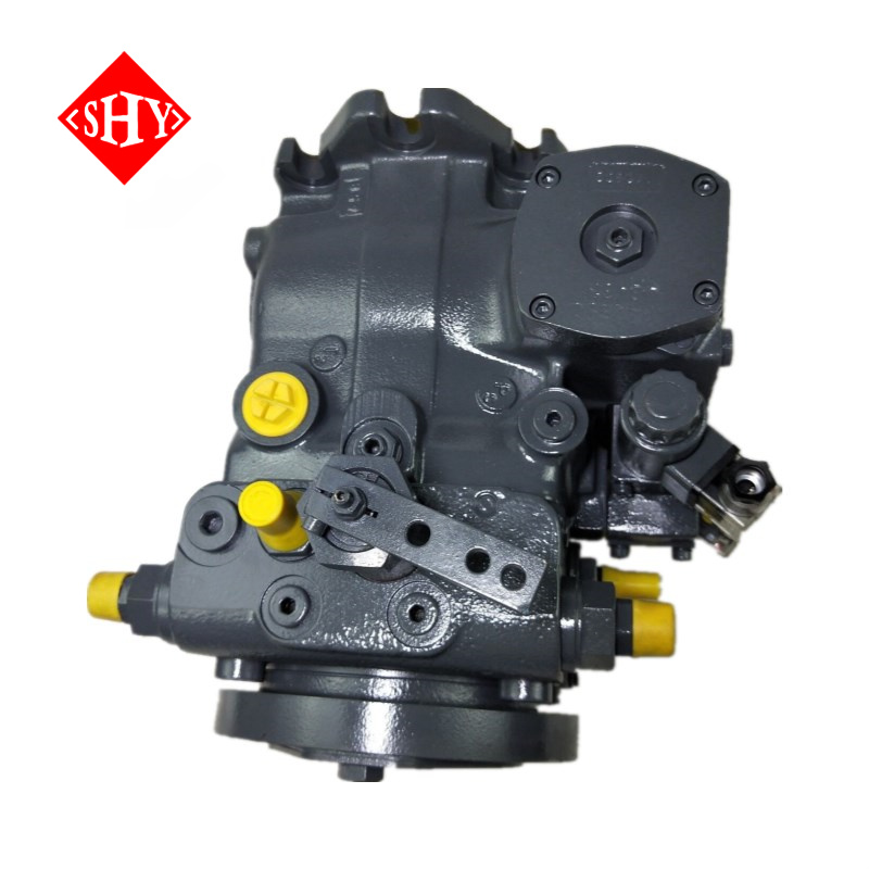
The control module acts as the brain of the hydrostatic drive. It dictates how the swashplate responds to operator inputs or automated machine commands. Available control methods include NV (no control), DG (hydraulic control, direct operated), EZ (two-point electrical), HD (hydraulic proportional), HW (mechanical proportional), EP (electrical proportional), and DA (speed-dependent). Selection depends entirely on the machine's regulation systems and the required precision of the operation. Swapping a pump with the wrong control module will render the machine inoperable, as the input signals will not match the mechanical actuation requirements.
Mechanical lever (HW) controls alter the swashplate angle via a direct physical linkage connected to the operator's joystick or pedal. As the lever moves, a control spool shifts. This directs charge pressure to the stroking cylinder, which tilts the swashplate. Hydraulic direct control (HD) operates similarly but uses a low-pressure hydraulic pilot signal from a remote joystick to shift the control spool. Hydraulic control with D pressure (DG) uses a direct pressure signal to set specific displacement points. Versions without control modules (NV) are supplied for custom integrations where the OEM mounts a proprietary control block directly to the pump housing.
These controls offer exceptional reliability in harsh environments lacking electrical infrastructure. In underground mining or heavy dirt construction, mechanical linkages and hydraulic pilot lines remain immune to water ingress, vibration-induced electrical shorts, and sensor failures. The trade-off is a slightly slower response time and less precision compared to electronic counterparts. Mechanical wear in linkages can introduce hysteresis. This means the pump may not return to exact neutral perfectly, requiring occasional manual calibration of the mechanical zero point to prevent machine creep. Technicians must regularly inspect rod ends and bell cranks for excessive play that could compromise control accuracy.
Integration of proportional solenoids (EP) allows for infinitely variable displacement control using a Pulse Width Modulated (PWM) electrical signal. As the current to the solenoid increases, the swashplate angle increases proportionally. Two-point electrical controls (EZ) use simple on/off solenoids to switch the pump between zero displacement and maximum displacement. This setup proves useful for basic auxiliary drives or fan circuits. Speed-dependent controls (DA) utilize a cartridge valve that responds directly to the prime mover's engine RPM. As engine speed increases, the control pressure rises, automatically stroking the pump to accelerate the machine.
These modules interface seamlessly with modern PLCs and CAN bus systems for automated, highly precise load-sensing and speed regulation. In advanced agricultural tractors or automated guided vehicles, EP controls allow the machine's central computer to manage traction control, anti-stall functions, and precise inching movements. The electronic control unit can monitor system pressure and instantly destroke the pump if an overload condition is detected. This prevents engine stall and optimizes fuel consumption during heavy digging or lifting cycles. Troubleshooting these systems requires a multimeter to verify coil resistance and PWM signal integrity at the harness connector.
Applying the correct pump geometry to the circuit architecture is non-negotiable. The A4VG is engineered exclusively for closed-circuit hydrostatic transmissions. In a closed circuit, the fluid returning from the hydraulic motor flows directly back into the pump inlet, rather than returning to a central reservoir. This creates a continuous, high-pressure loop capable of transmitting power in both directions simply by stroking the pump over center. Using a closed-circuit pump in an open-circuit application will result in immediate failure due to the lack of proper porting and suction characteristics. The internal passages are not sized to draw cold, thick oil from a distant tank.
When evaluating open-circuit systems, the A4VSO40-355 hydraulic piston pump serves as the proper alternative. Contrasting the closed-circuit design with the open-circuit A4VSO series highlights distinct operational differences. The A4VSO draws fluid from a large atmospheric reservoir and pumps it to directional control valves. These valves then route the fluid to cylinders or motors. The return fluid goes back to the tank, not the pump. The A4VSO features robust suction porting designed to pull oil from the tank without cavitating. The closed-circuit counterpart relies on its integrated charge pump to force oil into the closed loop.
When deciding between the two, evaluate the primary function of the hydraulic system. Pivot to the open-circuit alternative for applications like industrial hydraulic presses, large-scale open-loop cylinder actuation, or central hydraulic power units where multiple independent functions draw from a single pressure source. Stick with the closed-circuit design for mobile hydrostatic transmissions, track drives, and rotary milling heads where compact, bidirectional, high-pressure continuous rotation is required. Mixing these architectures leads to severe cavitation, overheating, and immediate destruction of the rotating group.
Installing a high-performance axial piston pump requires strict adherence to hydraulic fundamentals. The tolerances between the piston shoes, the swashplate, and the valve plate are measured in microns. Any deviation from standard operating parameters regarding fluid condition, temperature, or startup procedures will severely degrade the pump's lifespan. Field replacements often fail within the first fifty hours because technicians neglect to address the root cause of the original pump's failure, such as a contaminated reservoir or a blocked heat exchanger.
Strict ISO contamination codes are required to prevent scoring of the internal components. Closed-circuit systems should maintain fluid cleanliness levels of at least ISO 4406 20/18/15. The first number represents particles larger than 4 microns, the second represents particles larger than 6 microns, and the third represents particles larger than 14 microns. Particulate contamination acts as a lapping compound, eroding the hydrostatic bearing surfaces between the cylinder block and the valve plate. This erosion increases internal leakage, reducing volumetric efficiency and generating excessive heat. High-pressure inline filters and charge pump suction filters must be replaced at exact OEM intervals. Implementing off-line kidney loop filtration during maintenance windows further mitigates contamination risks.
Thermal management is a critical risk factor in closed circuits. Because the fluid continuously loops between the pump and the motor, heat generated by friction and internal leakage accumulates rapidly. Properly sized hot oil shuttle valves must be integrated into the motor or the pump block. These valves bleed a small percentage of hot oil out of the low-pressure side of the loop, directing it to the pump case and then through a heat exchanger before returning to the reservoir. The orifice size inside the flushing valve determines the exact volume of oil removed from the loop. Failure to flush the loop adequately will cause the oil viscosity to drop, leading to metal-to-metal contact and catastrophic failure.
Initial startup requires rigorous commissioning protocols to prevent dry running or cavitation. Follow these exact steps during installation:
Fill the pump case manually with clean, filtered hydraulic fluid through the highest case drain port before rotating the input shaft.
Bleed all trapped air from the control lines and the main loop to prevent erratic swashplate movement and cavitation damage to the valve plate.
Run the prime mover at low idle upon initial engine startup without engaging the transmission.
Verify that the charge pressure reaches the specified minimum (typically 20-25 bar) before applying any load to the hydrostatic drive.
Monitor case drain flow and temperature during the first hour of operation to ensure internal leakage remains within acceptable limits.
Locate the OEM data plate on your current hydraulic pump and record the complete alphanumeric R-number to ensure exact displacement and configuration matching.
Cross-reference your machine's hydraulic schematic to confirm the required control module type and verify compatibility with existing joysticks or electronic control units.
Inspect the existing hydraulic reservoir, filters, and lines for metal contamination, and execute a complete system flush if the previous unit failed mechanically.
Measure the required spline shaft dimensions and mounting flange specifications on the machine bell housing before finalizing any replacement order.
A: Series 32 operates at a nominal pressure of 400 bar and a peak of 450 bar, commonly used in legacy and medium-duty equipment. Series 40 handles higher demands with a nominal pressure of 450 bar and a peak of 500 bar, offering higher power density and a more compact footprint for modern heavy-duty applications.
A: The R-number identifies the exact manufacturing specifications of the pump, including displacement, rotation direction, shaft spline, control module, and relief valve settings. Matching this number ensures the replacement pump is a direct, compatible fit for your specific machine without requiring modifications.
A: No. This pump is designed exclusively for closed-circuit hydrostatic drives. It lacks the suction porting required to draw fluid directly from an atmospheric reservoir. For open-circuit applications, models like the A4VSO are required to prevent severe cavitation.
A: The integrated boost pump, or charge pump, replenishes hydraulic fluid lost to internal leakage. It maintains positive pressure in the low-pressure side of the closed loop to prevent cavitation and provides the necessary pilot pressure to operate the swashplate control module.
A: HD (Hydraulic Direct) controls use a low-pressure hydraulic pilot signal from a joystick to mechanically shift the pump's control spool. EP (Electrical Proportional) controls use an electrical PWM signal to activate proportional solenoids, allowing for precise, automated control via a machine's electronic control unit.
A: DA (speed-dependent) controls automatically adjust the pump's displacement based on the prime mover's engine RPM. As engine speed increases, a cartridge valve increases the control pressure, stroking the pump to accelerate the machine without requiring separate operator input for the transmission.


