





| Quantity: | |
|---|---|


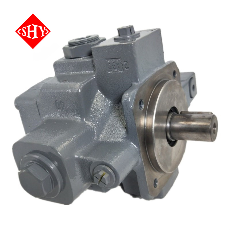
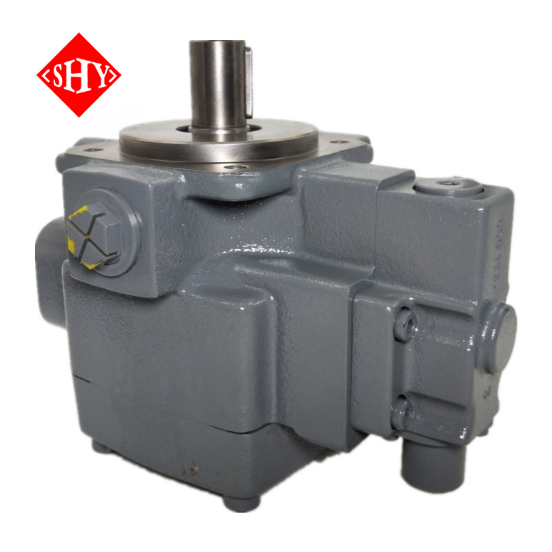
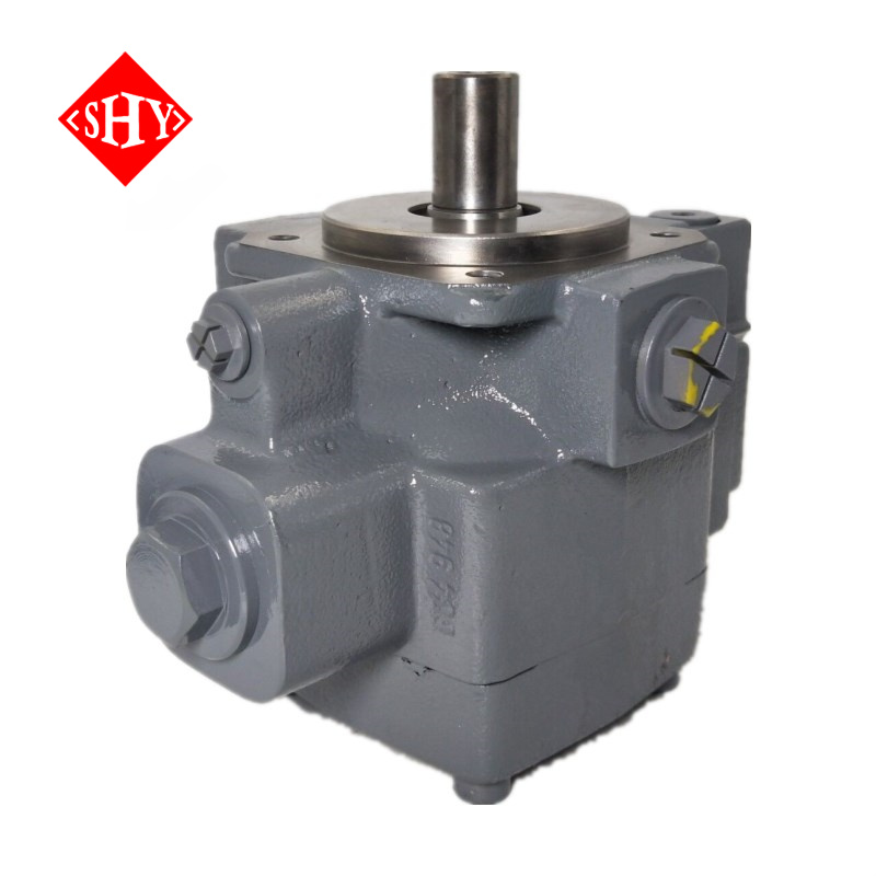
Engineered for the most demanding industrial environments, the 1PV2V4 V4 Series represents a significant leap forward in fluid power technology. This variable volume hydraulic vane pump is specifically designed to drastically optimize energy consumption while delivering precise, reliable fluid delivery across complex manufacturing cycles. By integrating an advanced variable control mechanism, the pump intelligently reduces energy draw during idle or partial-load periods. This direct reduction in power usage ensures your facility operates at peak efficiency, effectively lowering overall operational costs without compromising output. Running your hands along the exterior, you can immediately feel the cold, solid density of the heavy-duty, industrial-grade cast housing. Built with precision-machined mounting faces, this exterior shell is explicitly engineered to withstand the continuous vibrations, mechanical shocks, and intense stresses inherent in heavy manufacturing environments.

Internally, the pump utilizes advanced hydrodynamically lubricated sleeve bearings alongside meticulously bronze-coated control plates. These premium internal components work in perfect tandem to create highly favorable frictional characteristics. By minimizing internal metal-on-metal wear and significantly reducing heat generation, the structural integrity of the pump is preserved, extending the lifecycle of the equipment well beyond standard industry expectations. Operators and maintenance personnel walking the factory floor will immediately notice the remarkably low noise level during operation. Instead of a harsh mechanical grind, the pump emits a smooth, quiet hum that reflects its optimized internal fluid dynamics and perfectly balanced rotor assembly. This acoustic optimization is a crucial factor for improving workshop conditions, protecting worker hearing, and ensuring strict compliance with stringent occupational health and environmental standards.

Maintaining absolute control over fluid dynamics is essential for preventing production delays. The V4 series excels in providing instant, accurate fluid delivery tailored to specific machinery demands.
Rapid Dynamic Response: Featuring exceptionally short control times and remarkably low hysteresis, the hydraulic system reacts instantly to sudden load changes. This ensures your operations maintain consistent pressure and flow without any perceptible lag.
Universal Compensator Design: A single, highly adaptable compensator perfectly accommodates all displacements and controllers (including C, D, W, and E types). This modular approach simplifies inventory management and accelerates maintenance protocols.
Customizable Output: Optional control of pressure and flow is available upon request, allowing procurement teams to specify exact operational parameters tailored to unique machinery requirements, ensuring optimal integration.

The following technical data sheet outlines the precise performance capabilities, dimensional specifications, and operating limits of the V4 series. These parameters—ranging from displacement volumes and nominal pressures to permissible fluid temperature ranges—are critical for engineers sizing components for complex hydraulic circuits. Adhering to these exact specifications guarantees optimal performance, prevents premature component fatigue, and ensures the pump delivers the exact volumetric efficiency required for your specific industrial application. Reviewing these figures allows system designers to accurately predict performance outcomes under varying load conditions.

General | |||||||
Construction | Variable vane pump | ||||||
Type | V4 | ||||||
Mounting | Flange mounting | ||||||
Connections | Threaded or flanged, dependent on size of unit and model designation | ||||||
Installation position | Optional, preferrably horizontal | ||||||
Shaft loading | Radial and axial forces cannot be accepted | ||||||
Direction of rotation | Clockwise (viewed on shaft end) | ||||||
Speed range | nmin bis nmax | rpm | 900 to 1800 | ||||
Size | 20 | 32 | 50 | 80 | 125 | ||
Drive power (n = 1750 rpm) | Peff | HP (kW) | 13.8 (10.3) | 23.5 (17.5) | 37.34 (27.8) | 51.8 (38.6) | 71.7 (64) |
Torque | Tmax | lb-ft (Nm) | 166.69 (228) | 216.84 (294) | 376.16 (510) | 376.16 (510) | 723.52 (1330) |
Weight (with pressure control C1) | m | lbs. (kg) | 51.79 (23.5) | 68.32 (31) | 94.33 (42.8) | 123.42 (56) | 211.58 (98) |
Hydraulic | |||||||
Size | 20 | 32 | 50 | 80 | 125 | ||
Displacement | Veff | in3 (cm3) | 1.26 (20.7) | 2.11 (34.5) | 3.37 (55.2) | 5.05 (82.8) | 7.79 (127.6) |
Max. Flow at n = 1750 min-1; p = 145 PSI (10 bar) | Q | GPM (L/min) | 9.25 (35) | 16.9 (64) | 24.3 (92) | 38 (144) | 57.7 (218) |
Nominal pressure | pN | PSI(bar) | 2320 PSI (160 bar) | ||||
Operating pressure (absolute) | |||||||
Inlet | p | PSIA (bar) | 12 PSIA to 36 PSIA (0.8 to 2.5 bar) | ||||
Outlet | p | PSI (bar) | 2320 PSI (up to 160 bar) | ||||
optimum adjustable | |||||||
Compensator pressure range | pNH | PSI (bar) | 580 to 2320 PSI (40 to 160)1 | ||||
Leakage outlet, max | p | PSI (bar) | 29 (2) | ||||
Fluid | HLP-mineral oils petroleum; phosphate-ester (HFD-R Please observe the specifications in data sheet RA 07 075! | ||||||
Fluid temperature range ° | °F (°C) | 14 to 158 °F (–10 to +70 °C) (note permissible viscosity range) | |||||
Viscosity range | v | SUS (mm2/s) | 75 to 740 SUS (16 to 160 mm2/s) at operating temperature and deadhead pressure below 915 PSI (63 bar) 120 to 740 SUS (25 to 160 mm2/s) at operating temperature and deadhead pressure above 915 PSI (63 bar) max. 3720 SUS (800 mm2/s) when starting up when the pump is delivering max. 930 SUS (200 mm2/s) when starting up deadheaded | ||||
Maximum degree of fluid contamination | Class 18/15 according to ISO 4406 Therefore, we recommend a filter with a retention rate of ß20 ≥75. To ensure longer pump life, we recommend class 17/14 according to ISO 4406.Therefore, we recommend a filter with a retention rate of ß10≥100. | ||||||

Flexibility in system integration serves as a core advantage of the V4 series, allowing it to be precisely tailored to a vast array of industrial applications. Whether your facility utilizes standard mineral oils (HLP) or requires fire-resistant phosphate-ester (HFD-R) fluids for high-temperature environments, the availability of specific NBR and FPM sealing options ensures total chemical compatibility. This prevents fluid degradation and guarantees leak-free performance over the long term. The modular architecture provides extensive customization, offering various flange and threaded connections (SAE/BSP) that facilitate straightforward integration into existing piping layouts. Furthermore, multiple shaft configurations—including keyed shafts for standard coupling and splined shafts for high-torque, direct-drive setups—ensure secure mechanical power transmission. By utilizing the comprehensive ordering code structure detailed below, system designers can precisely configure mechanical, remote hydraulic, or multi-stage electrical pressure controls to match their exact operational demands.


1 PV 2 V4
2X or 3X or 4X:
2X(Size 20 and Size 50): Series 20 to 29 : 20、21、22、23、24、25、26、27、28、29(20 to 29, externally interchangeable)
3X(Size 32 and Size 80):Series 30 to 39 : 30、31、32、33、34、35、36、37、38、39(30 to 39, externally interchangeable)
4X(Size 125):Series 40 to 49:40、41、42、43、44、45、46、47、48、49(40 to 49, externally interchangeable)
20 or 32 or 50 or 80 or 125
20:Size 20,Veff = 20.7 cm3
32:Size 32,Veff = 34.5 cm3
50:Size 50,Veff = 55.2 cm3
80:Size 80,Veff = 82.8 cm3
125:Size 125,Veff = 127.6 cm3
R or L: Direction of Rotation(Viewed from Shaft End):R:Clockwise;L:Anti-clockwise
A or E or F or G or W:
A:front shaft keyed metric
E:front shaft end keyed metric - rear shaft end splined
F:front shaft splined - rear shaft end splined
G:front shaft splined
W:front shaft keyed SAE
12 or 16 or 15 or 27 or 36 or 07:
12:Size 20, 32, 50: suction and pressure ports: SAE threaded
16:Size 80: suction port: SAE flange;pressure port: SAE thread;
15:Size 125: suction and pressure ports: SAE flanges Model with mounting for servo orifice on pressure port
27:Size 20, 32, 50: suction port: BSP thread
36:Size 80: suction port: SAE flange
07:Size 125: suction port: SAE flange
M or V or K:
M:NBR-seals, suitable for use with mineral oils (HLP) to DIN 51524 part 3 mineral oils (HLP)
V:FPM-seals, suitable for use with phosphate-ester (HFD-R)
K:NBR-seals and FPM shaft seal
C or D or E or W or N:
C:pressure control-mechanic adjustable
D:pressure control-remote hydraulic adjustable
E:pressure control-remote electric adjustable
W:pressure control 2 stage electric switchable
N:flow control-mechanical flow setting
1 or 3 or 5 or 7:
1:setting screw
3:lockable rotaryhand knob with scale
5:setting screw and K-plate for minimum start pressure
7:lockable rotary hand knob with scale and K-plate
16:up to 2320 PSI (160 bar) optimum range 580 to 2320 PSI (40 to 160 bar) . Other stall pressure settings . Details in clear text
M or A:
M:without setting screw
A:with setting screw
1:without valve
A complete model, for example:1PV2V4-30/125RA07MCO-16A1

The 1PV2V4 V4 Series is engineered to serve as the reliable heart of complex manufacturing systems. It is extensively deployed in heavy-duty machine tools, precision injection molding machines, and large-scale metallurgical equipment. In these high-intensity environments, the pump delivers a continuous, pulsation-free flow that guarantees the smooth actuation of heavy cylinders and high-torque hydraulic motors. For injection molding applications, this precise fluid delivery directly translates to accurate clamping force maintenance and highly repeatable injection speeds, ensuring consistent part quality with every cycle. In metallurgical plants, the durable structural design endures extreme ambient temperatures and continuous duty cycles without faltering, providing a dependable power source for critical material handling and processing equipment.


To maintain the precision tolerances of the hydrodynamically lubricated bearings and bronze-coated plates, strict adherence to fluid cleanliness is paramount. Our quality control protocols align with rigorous ISO 4406 standards. We strongly advise maintaining a maximum fluid contamination level of Class 18/15, utilizing a high-efficiency filter with a retention rate of ß20 ≥75. For facilities aiming to maximize the operational lifecycle and minimize unexpected downtime, upgrading to a Class 17/14 cleanliness standard with a ß10 ≥100 filter provides the ultimate protection against particulate abrasion. During maintenance, the visual clarity of well-filtered hydraulic fluid and the smooth, unmarred surfaces of the internal components serve as proof of effective filtration. This proactive approach to fluid management ensures the pump maintains its low hysteresis, rapid response characteristics, and exceptional volumetric efficiency year after year, ultimately delivering an outstanding return on investment.