






| Quantity: | |
|---|---|


– easy commissioning due to automatic bleed facility, ensuring immediate system readiness without manual air purging delays. Operators can physically hear the swift, uninterrupted intake of fluid, bypassing the usual sputtering associated with trapped air pockets.
– low noise level operation, achieved through optimized vane chamfering and precision stator matching, keeping flow pulsation below 3% for a quiet, stable working environment that minimizes operator auditory fatigue on the factory floor.
– high bearing life because of hydrodynamically lubricated plain bearings, complemented by high-hardness alloy steel rotors and self-lubricating copper-based vanes for extended fault-free longevity under heavy loads. The dense, weighty construction of the rotor assembly provides tangible proof of its industrial resilience.
– bronze-faced starting and control plates, giving low friction characteristics during marginal lubrication conditions, protecting the core mechanism during cold starts when the hydraulic oil viscosity is at its thickest.

Technical data | Symbol | Units | Nominal sizes | |||
V3/12 | V3/25 | V3/40 | V3/63 | |||
Nominal displacement | Vg | cm3/rev | 8.5 | 19 | 32 | 47 |
Nominal output flow at n = 1450 rpm, p = 1 MPa | Qn | L/min | 13 | 27.5 | 47 | 67 |
Speed range | n | min–1 | 950 up to 1800 | |||
Spring type | C25, C40, C63, C100 | |||||
Pressure range | p | bar | 12 ... 25 20 ... 40 30 ... 63 50 ... 100 | |||
Operating pressure: input outlet | p p | bar bar | 0.2 (underpressure) up to 5 (overpressure) max. 100 – continuous op. pressure | |||
Leakage port | p | bar | max. 2 | |||
Max. torque (drive shaft) | Mk | Nm | 54 | 61.8 | 235 | 353 |
Hydraulic medium | mineral oils HLP DIN 51 524 part 2 | |||||
Temperature range | tpo | oC | –10 up to +70 | |||
Fluid filtration | µm | 25 absolute (ß20≥100) We recommend 10 µm in order to achieve long working life, with heavy loading, high duty and low viscosity | ||||
Oil viscosity range | n | m2/s | 16 ·10–6 up to 160 ·10–6 at operation temperature and zero stroke pressure < 63 bar 25 ·10–6 up to 160 ·10–6 at operation temperature and zero stroke pressure > 63 bar max. 800 ·10–6 when starting up and oil delivering max. 200 ·10–6 when starting up at zero stroke | |||
Efficiency | see curves | |||||
Weight | m | kg | 6.25 | 11.1 | 26.5 | 29.5 |
Understanding the standard program configuration ensures that procurement teams select the exact specifications required for their specific machinery setups, avoiding costly mismatches.
1PV: One-flow pump with variable geometrical displacement, delivering precise fluid control.
2:Flange mounting, ensuring a vibration-resistant, secure physical connection to the primary drive.
V3: Vane pump type V3, optimized for industrial energy efficiency.
30 or 40:
Series 30:nominal size 40; 63
Series 40:nominal size 12; 25
12 or 25 or 40 or 63:
Nominal size 12 – 8.5 cm3 /rev
Nominal size 25 – 19 cm3 /rev
Nominal size 40 – 32 cm3 /rev
Nominal size 63 – 47 cm3 /rev
R or L: Direction of Rotation(Viewed from Shaft End):R:Clockwise;L:Anti-clockwise
A: One cylindrical shaft end
01: Connection both suction and displacement through pipe cylindrical threads
M: Operating fluid mineral oil (DIN 51 524)
C: Adjustment of operating pressure by adjusting screw with external hexagonal
Pressure at zero stroke:100 bar or 63 bar or 40 bar or 25 bar
A: Geometrical displacement adjustment by the adjusting screw with external hexagonal
1: With bleed valve
A complete model, for example : 1PV2V3-30/63RA01MC25A1


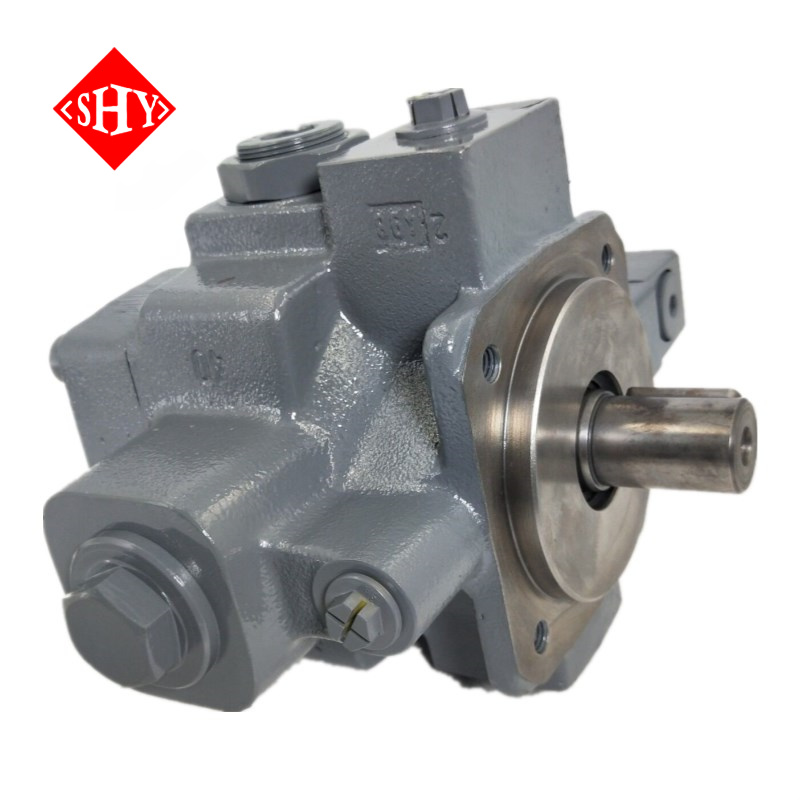
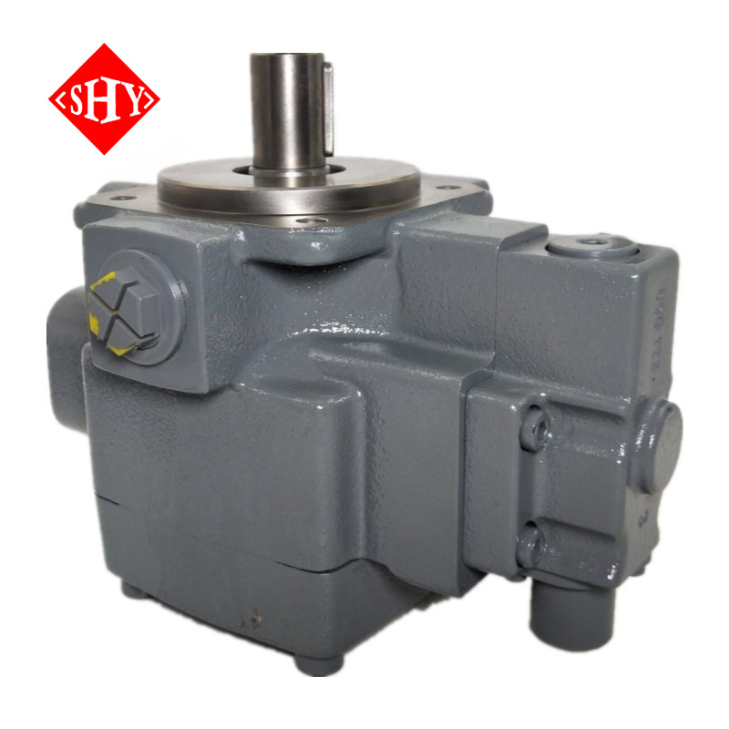
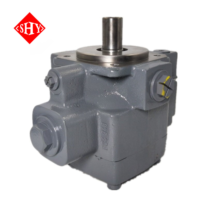
The 1PV2V3 series is engineered as a reliable core component in advanced hydraulic systems, widely applied in CNC machine tools, injection molding machinery, die-casting equipment, and heavy construction machinery. These pumps offer precise flow regulation and robust performance under diverse operating conditions, making them ideal for applications requiring dynamic pressure control and energy efficiency. By utilizing an advanced pressure compensation variable mechanism, this unit adaptively adjusts flow rates, which can significantly reduce system energy consumption by 20% to 30% compared to traditional fixed-displacement alternatives. This translates into a measurable improvement in operational cost-efficiency for large-scale facility managers.
The solid, cool metallic touch of the cast iron housing speaks to its industrial-grade durability, built to withstand the rigorous demands of continuous heavy-duty cycles. Furthermore, adopting standard flange and shaft end designs, this series provides exceptional interchangeability. It seamlessly integrates into existing setups, allowing for direct, modification-free replacement of mainstream international variable vane pumps, thereby drastically lowering system upgrade and retrofit costs.


Working Pressure Range: 12–100 bar (with peak up to 120 bar), providing the muscular force necessary for demanding industrial pressing and lifting tasks, delivering a consistent thrust you can rely on.
Displacement Range: 10–100 cc/rev, with variable adjustment capability that adapts instantly to shifting load requirements, ensuring fluid delivery matches exact mechanical demands without waste.
Model Designation Example: Suffix “MC25A1” indicates a precise displacement of 25 cc/rev, simplifying procurement and system integration for maintenance engineers.
Adjustment Precision: ±2% accuracy, response time ≤0.5 seconds—ideal for precision control environments where micro-second delays impact production quality and material integrity.
Efficiency Standards: Volumetric efficiency ≥92%, mechanical efficiency ≥85%, surpassing industry benchmarks for vane pump energy performance, reducing thermal waste, and keeping the external casing noticeably cooler during prolonged operation.
Temperature Management: Designed for continuous operation with oil temperature maintained at ≤65°C (cooling system recommended to preserve fluid viscosity and protect internal seals from premature degradation).
Construction: Cast iron housing with single-stage design, compatible with standard hydraulic oil media. Furthermore, it boasts an industrial-grade IP65 equivalent protection standard, allowing it to thrive in dusty, moisture-heavy outdoor engineering environments, shielded by its rugged exterior.


The flow regulation mechanism of the 1PV2V3 series is designed with operator ergonomics and precise control in mind. Flow is easily adjusted via an integrated handle system that provides immediate tactile feedback. When operators grip the adjustment ring, they will feel a smooth, resistance-free rotation, allowing for micro-adjustments without specialized tools. The distinct metallic click of the locking mechanism provides auditory confirmation that the setting is secure.
For light-load stabilization: Operators can adjust the grey lock nut and rotate the yellow ring clockwise in approximately 15° increments. Each increment offers a distinct, satisfying click, ensuring that the exact desired displacement is locked in securely, preventing accidental drift during operation.
Under heavy-load stall conditions: Use the blue lock nut and red adjusting ring similarly to restore stable pressure output. The firm resistance of the heavy-duty lock nut guarantees that even under severe machine vibrations, the pressure settings remain absolute. This intuitive, color-coded adjustment system significantly reduces setup times and minimizes operator error on the factory floor.


Every single pump undergoes 100% dynamic load testing for pressure, flow accuracy, and noise emissions before leaving our facility. This rigorous protocol ensures industrial-grade, zero-defect delivery. Manufactured in strict compliance with ISO 9001 quality management systems and CE safety standards, these units comfortably meet the stringent entry requirements of premium global industrial markets.
We provide an extended warranty period backed by rapid-response technical support. A comprehensive inventory of standardized wear parts—such as high-hardness rotors and copper-based vanes—is maintained at all times. This proactive approach drastically reduces equipment downtime, keeping your production lines moving without prolonged interruptions.
To protect the precision-engineered components during cross-border transit, each unit receives multiple anti-rust treatments and is secured within high-strength, fumigation-free wooden export crates. This guarantees the product arrives free from moisture damage or impact abrasions. Additionally, we offer deep OEM/ODM customization services, adapting the pump for specialized hydraulic fluids, non-standard mounting dimensions, or extreme environmental conditions to perfectly suit your complex engineering requirements.