


Views: 0 Author: Site Editor Publish Time: 2026-09-01 Origin: Site


Specifying the wrong hydraulic pump leads directly to system cavitation, premature wear, excessive energy consumption, and unplanned downtime. At its core, this component performs a fundamental function. It converts mechanical energy from a prime mover into hydraulic fluid power. The engineering challenge lies in matching this energy conversion process to specific application requirements. You must balance pressure capabilities, volumetric efficiency, and fluid compatibility. Doing this correctly prevents over-engineering the system or exceeding budget constraints.
This guide provides a technical, decision-focused breakdown of the primary pump categories. We explore their operational trade-offs in detail. You will learn how to evaluate these components for specific industrial or mobile deployments based on rigorous engineering criteria.
The "Big Three" Categories: While numerous variants exist, the vast majority of hydraulic systems rely on gear, vane, or piston pumps.
Gear Pumps: Deliver rugged reliability and high contamination tolerance at a low initial cost, but sacrifice volumetric efficiency at higher operating pressures.
Vane Pumps: Provide exceptional flow consistency and low-noise operation, making them the standard for medium-pressure, indoor industrial environments.
Piston Pumps: Offer maximum pressure capabilities, peak volumetric efficiency, and variable displacement options, essential for heavy-duty mobile and closed-loop systems.
Evaluation Criteria: Final specification must be dictated by lifecycle operational expenses, ISO fluid cleanliness requirements, and precise pressure/flow mapping, rather than upfront purchase price alone.
Selecting the correct fluid power source begins with defining strict baseline requirements. You must establish the required flow rate, measured in gallons per minute (GPM) or liters per minute (LPM). Flow dictates actuator speed. Next, determine the maximum operating pressure, measured in PSI or Bar. Pressure determines actuator force. You calculate the required hydraulic horsepower by multiplying GPM by PSI and dividing by 1714. This formula gives you the exact mechanical power needed from your electric motor or diesel engine.
Finally, evaluate the duty cycle. A continuous duty cycle generates significant heat and requires robust internal components. Intermittent duty cycles allow for lighter-duty selections. Failing to map these three metrics accurately guarantees poor system performance. On a job site, an undersized unit will stall under load, while an oversized unit will generate excessive heat and waste energy.
Understanding displacement is critical for system architecture. Fixed displacement pumps deliver a constant volume of fluid per shaft rotation. Flow output changes only when the input shaft speed changes. This simplicity makes them reliable but often requires relief valves to manage excess flow. Pushing excess fluid over a relief valve generates massive amounts of heat and wastes prime mover horsepower.
Variable displacement pumps adjust their flow output internally while maintaining a constant shaft speed. They use compensators to alter internal geometry. A pressure-compensated unit will destroke and stop producing flow when the system reaches a predetermined pressure. A load-sensing unit communicates with directional valves to provide only the exact flow and pressure required by the active function. This capability allows the system to match exact flow demands, reducing wasted energy. Your choice here dictates the complexity of your entire hydraulic circuit.
Procurement often focuses heavily on the initial purchase price. This approach ignores the reality of fluid power systems. A cheaper component might save money upfront but require frequent replacements. It may also suffer from lower volumetric efficiency. Lower efficiency means the prime mover works harder, consuming more electricity or diesel fuel over the machine's lifespan.
Conversely, a high-efficiency component carries a larger upfront cost. However, it significantly reduces energy consumption and maintenance intervals. You must evaluate the total financial impact over a five-to-ten-year operating window. Factoring in the cost of machine downtime, replacement labor, and energy draw provides a realistic picture of the component's true operational expense.
The fundamental design of your hydraulic circuit dictates the required pump category. Open-loop systems draw fluid from a reservoir, push it through directional valves to actuators, and return it to the reservoir. These systems typically utilize fixed displacement gear or vane designs. The reservoir acts as a massive heat sink and contamination settling tank.
Closed-loop systems route fluid directly from the pump to a hydraulic motor and back to the pump intake. This architecture requires highly precise control over flow direction and volume. Closed-loop designs almost exclusively rely on variable displacement piston designs equipped with integrated charge systems. The charge system replenishes fluid lost to internal leakage and provides cooling flow.
Gear designs operate on a straightforward positive displacement principle. They use interlocking mechanical gears to move fluid. As the gears unmesh at the inlet, they create a localized vacuum. Atmospheric pressure pushes fluid into this void. The fluid travels around the outer perimeter of the gears, trapped between the gear teeth and the housing. As the gears mesh again at the outlet, the volume decreases, forcing the fluid into the system.
External gear designs use two identical gears rotating against each other. One is the drive gear attached to the input shaft, and the other is the idler gear. Internal gear designs feature a smaller drive gear rotating inside a larger internal ring gear. A crescent-shaped partition separates the inlet and outlet ports. Internal designs generally offer smoother, quieter operation due to the gradual meshing of the gear teeth.
These components are celebrated for their durability. They typically handle maximum operating pressures up to 3,000 or 4,000 PSI. Their volumetric efficiency is moderate, usually hovering between 85% and 90% when new. The defining advantage of this category is contamination tolerance. The robust mechanical clearances allow them to pass particulate matter that would instantly destroy more sensitive designs.
They survive in harsh, dirty environments where filtration maintenance is poor or inconsistent. Cast iron housings provide higher pressure capabilities and better resistance to pressure spikes. Aluminum housings offer weight savings for mobile applications where every pound matters.
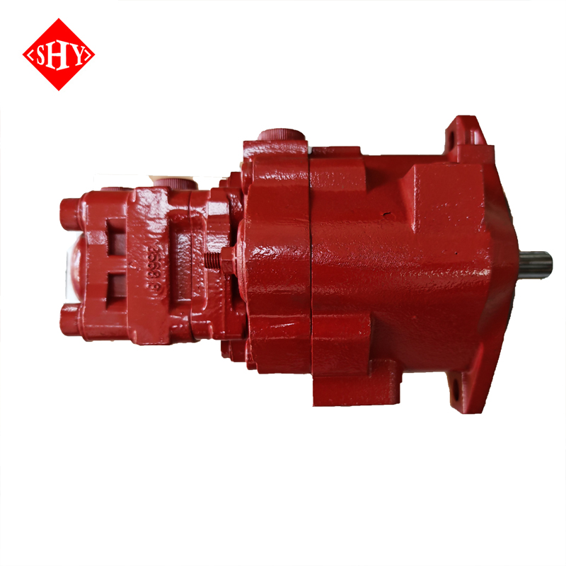
You will find these units dominating the mobile equipment sector. They power the primary hydraulic functions on agricultural tractors, skid steers, and material handling equipment. They thrive in environments demanding reliable, brute-force fluid power. For compact machinery, engineers frequently specify the PVD-00B/PVD-0B/PVD-1B gear pump series. This specific series provides an excellent balance of compact housing dimensions and reliable power output, making it ideal for mini-excavators and tight-clearance mobile applications.
Despite their ruggedness, these units have distinct drawbacks. They generate higher operational noise levels compared to other categories, often producing a loud, high-pitched whine. They are strictly fixed displacement devices. You cannot adjust their flow output without changing the drive speed.
Furthermore, they suffer from gradual efficiency loss. As the gear faces and housing side plates wear down from normal use, internal leakage increases. This wear reduces effective flow output and increases heat generation over time. When you tear down a failed unit, you will typically find deep scoring on the housing walls where the gears have machined away the metal.
These units utilize a cylindrical rotor mounted inside a larger circular cam ring. The rotor contains radial slots housing flat, rectangular vanes. As the input shaft turns the rotor, centrifugal force pushes the vanes outward against the cam ring surface. Because the rotor sits eccentrically within the ring, the volume between the vanes expands and contracts during rotation.
Fluid enters the expanding chambers, travels along the ring, and exits as the chambers collapse. Balanced designs utilize an elliptical cam ring with two inlets and two outlets. This configuration places the high-pressure outlet ports opposite each other, canceling out internal side loads on the drive shaft bearings and extending component life significantly.
This category occupies a specific performance sweet spot. They excel in medium-pressure bands, typically operating efficiently up to 2,500 or 3,000 PSI. Their primary advantage is exceptional flow consistency. The sliding vane mechanism produces very low flow pulsation, resulting in smooth actuator movement.
Additionally, they offer significant acoustic advantages. They operate much more quietly than gear designs, which is a critical requirement for indoor factory environments. The vanes rely on hydrodynamic lubrication, meaning a thin film of oil must constantly separate the vane tip from the cam ring to prevent metal-to-metal contact.
Industrial manufacturing relies heavily on this technology. You will see them installed on die-casting machines, plastic injection molding equipment, and indoor industrial presses. These applications demand smooth, consistent force without deafening factory workers. When evaluating options for high-performance, low-noise industrial tasks, the PV2R1-8-F-RAA-40 vane pump serves as an excellent benchmark. It demonstrates the precise flow delivery and acoustic dampening required for modern automated manufacturing lines.
The precision of the sliding vanes introduces vulnerabilities. These units are highly sensitive to fluid contamination. Even small particulates can wedge between the vane and the rotor slot, causing the vane to stick. When a vane sticks, it fails to track the cam ring, leading to internal leakage and rapid failure.
They also have strict viscosity constraints. If the hydraulic fluid is too cold and thick, the vanes may not extend fully, leading to poor suction and cavitation. Finally, they are generally unsuitable for high-shock load environments. Sudden pressure spikes can shatter the internal vanes or crack the cam ring.
Vane Pump Maintenance and Troubleshooting Guide | ||
Symptom | Potential Cause | Field Action Required |
|---|---|---|
Excessive Noise (Chatter) | Sticking vanes due to contamination | Inspect fluid cleanliness; replace cartridge kit |
Loss of Flow at High Pressure | Worn cam ring or vane tips | Measure internal clearances; rebuild unit |
Aeration (Whining Sound) | Air leak in suction line | Tighten inlet fittings; check shaft seal |
Overheating | Fluid viscosity too high or low | Verify fluid grade matches ambient temperature |
This category represents the pinnacle of fluid power engineering. Axial designs arrange pistons in a circular array parallel to the drive shaft. In a swash plate axial design, the pistons rotate against an angled plate. The angle of this swash plate dictates the piston stroke length, and therefore, the displacement. Bent-axis designs achieve the same result by angling the entire cylinder block relative to the drive shaft.
Radial designs arrange pistons outward from the drive shaft, like spokes on a wheel. An eccentric cam on the drive shaft pushes the pistons outward, while springs return them. Radial configurations excel at generating extreme pressures at lower shaft speeds, making them ideal for heavy industrial presses.
These units offer unmatched technical capabilities. They easily handle extreme pressure ratings, frequently operating continuously above 5,000 or 6,000 PSI. They deliver peak volumetric efficiency, often exceeding 95%. The tight machining tolerances between the pistons and the cylinder bores minimize internal leakage.
Their most critical feature is variable flow control. By adjusting the swash plate angle via mechanical, hydraulic, or electronic controls, the system can alter flow output instantly. This allows for load-sensing circuits that only generate flow when actuators demand it, drastically reducing wasted energy. They also feature a case drain line, which routes internal leakage back to the reservoir. Monitoring case drain flow is the most accurate way to gauge internal wear.
Heavy-duty applications demand this level of performance. They are absolute necessities in large construction excavators, mining equipment, aerospace flight controls, and hydrostatic transmissions. These machines require high power density and precise control. The A4VG28/40/56 axial piston pump is widely recognized as an industry standard for closed-loop hydrostatic drives. It provides the exact variable displacement control necessary for smooth vehicle propulsion and dynamic braking.
Adopting this technology requires overcoming significant barriers. The initial capital cost is substantially higher than simpler designs due to the complex internal machining. Maintenance requires specialized training and clean-room environments. You cannot rebuild these units on a dusty job site.
Most importantly, they demand absolute fluid cleanliness. The tight internal tolerances require strict adherence to ISO cleanliness codes. Poor filtration will destroy the brass slipper pads and valve plates within hours of operation. If the case drain line becomes restricted, internal pressure will blow out the main shaft seal.
Mobile hydraulic systems often require application-specific variants. Clutch pumps integrate an electromagnetic clutch on the input shaft, similar to an automotive air conditioning compressor. This allows the operator to engage or disengage hydraulic power via a dashboard switch, saving fuel when hydraulic functions are not needed. They are common on tow trucks and snowplows.
Dump pumps are specialized gear units designed for dump trucks and refuse vehicles. They integrate the pump, directional control valve, and relief valve into a single, compact cast-iron housing. This integration simplifies installation on Power Take-Off (PTO) systems where space is severely limited. Operators engage the PTO at specific engine RPMs to raise the dump bed, then disengage it for highway travel.
Not all pumps in a hydraulic circuit generate high-pressure power. Peristaltic and centrifugal designs serve critical auxiliary roles. Peristaltic designs use rollers to squeeze a flexible tube, moving fluid without the fluid ever touching internal mechanical parts. They are used for transferring highly corrosive or sensitive fluids.
Centrifugal designs use a spinning impeller to accelerate fluid outward. While they cannot generate high pressure, they move massive volumes of fluid. In large hydraulic circuits, centrifugal units act as charge pumps, keeping the main high-pressure inlet flooded to prevent cavitation. They also circulate fluid through offline cooling and filtration kidney loops, ensuring the main reservoir stays clean and cool.
Begin your shortlisting process by plotting your application requirements against component capabilities. Create a matrix with maximum pressure on the Y-axis and maximum flow on the X-axis. If your application requires 5,500 PSI, you immediately eliminate gear and vane categories. If you need 2,000 PSI with high contamination tolerance for a dirty environment, gear designs become the primary focus. This mapping exercise prevents wasting time evaluating unsuitable technologies.
The choice of hydraulic fluid heavily impacts component selection. Standard petroleum-based fluids work well with most internal materials. However, fire-resistant water-glycol fluids or synthetic esters require specific seal materials like Viton or EPDM to prevent seal degradation. Water-glycol fluids also have lower lubricity, which derates the maximum operating pressure of the pump.
Furthermore, you must evaluate the fluid's viscosity index. The fluid must remain thick enough at maximum operating temperature to maintain internal lubrication, but thin enough at cold startup to prevent cavitation. Piston designs generally require tighter viscosity control than gear designs.
System complexity dictates filtration requirements. You must align your filtration strategy with your component choice. Gear units can often survive with standard 10-micron return line filtration and an ISO 4406 cleanliness code of 21/19/16. Vane units require cleaner fluid, often necessitating 3-to-5-micron filtration and dedicated breather caps.
Piston units demand the highest level of cleanliness. Implementing piston technology without upgrading to high-efficiency glass-fiber media filters and offline kidney loop filtration is a guaranteed path to premature failure. They require an ISO code of 16/14/11 or better to protect the valve plates and piston shoes.
You must match the input shaft speed requirements with your prime mover. Standard AC electric motors typically run at 1,200 or 1,800 RPM. Most industrial hydraulic components are optimized for these speeds. Diesel engines in mobile equipment operate across a much wider RPM band, often from 800 to 2,500 RPM.
You must ensure the chosen component can handle the maximum engine speed without cavitating, while still delivering sufficient flow at engine idle. Check the manufacturer's suction velocity limits. If the pump spins too fast, it will pull a vacuum on the inlet line, causing dissolved air to implode against the internal metal surfaces.
Hydraulic Pump Category Comparison | ||||
Pump Category | Max Pressure Range | Volumetric Efficiency | Noise Level | Contamination Tolerance |
|---|---|---|---|---|
Gear | Up to 4,000 PSI | Moderate (85-90%) | High | Excellent |
Vane | Up to 3,000 PSI | Good (90-93%) | Low | Poor |
Piston | Up to 6,000+ PSI | Excellent (95%+) | Moderate | Very Poor |
Calculate your exact maximum pressure and flow requirements under full load to establish a baseline hydraulic horsepower target.
Determine the required displacement per revolution by dividing your target flow rate by your prime mover's operating RPM.
Establish a strict fluid cleanliness target based on the ISO 4406 code required by the most sensitive component in your proposed circuit.
Upgrade your reservoir filtration and breather caps if you are transitioning from a gear-based system to a piston-based system.
Consult with a certified fluid power engineer to verify your final sizing, confirm seal compatibility, and validate your suction line diameter.
A: Axial piston designs consistently deliver the highest volumetric efficiency. Their tight internal machining tolerances and precise piston-to-bore clearances minimize internal fluid leakage. Well-maintained piston units frequently achieve volumetric efficiencies exceeding 95% under high-pressure loads.
A: No. Fixed displacement units, like standard gear and most vane designs, have rigid internal geometries. Variable displacement requires specific internal mechanisms, such as an adjustable swash plate or a movable cam ring, which cannot be retrofitted into a fixed housing.
A: Fluid contamination is the leading cause of failure, causing abrasive wear on internal surfaces. Fluid starvation (cavitation) due to restricted inlet lines or cold, thick fluid is the second most common cause. Over-pressurization and excessive heat also rapidly degrade internal seals and bearings.
A: Choose external gear designs for higher pressure mobile applications where cost and ruggedness are priorities. Select internal gear designs for indoor industrial applications where low operational noise and smooth flow delivery are more important than achieving maximum pressure.
A: Most standard industrial vane units are rated for continuous operation between 2,500 and 3,000 PSI. Exceeding these limits forces the vanes too aggressively against the cam ring, causing rapid wear, excessive heat generation, and potential catastrophic vane breakage.
A: They offer precise variable displacement control and the ability to reverse fluid flow direction seamlessly. By tilting the swash plate over the center position, the pump reverses flow, allowing a hydrostatic vehicle to brake and reverse direction without directional control valves.


