


Views: 0 Author: Site Editor Publish Time: 2026-08-11 Origin: Site


A small hydraulic pressure pump operates as the mechanical heart of any fluid power system, taking mechanical input from an electric motor or combustion engine and converting it into hydrostatic energy. Field engineers and procurement teams often face a significant challenge: misunderstanding the internal mechanics of different pump designs leads to undersized components, system overheating, cavitation, and premature mechanical failure. These specification errors ultimately inflate downtime costs and ruin production schedules.
This technical evaluation guide breaks down the operating principles, design variations, and critical criteria required to specify the right pump for high-demand industrial applications. We will shift the focus from basic definitions to a rigorous breakdown of mechanical operations. By understanding the exact fluid dynamics and internal tolerances at play, you can properly match pump architecture to your specific load requirements and avoid catastrophic system failures.
Function Over Force: A hydraulic pump does not generate pressure directly; it generates flow. Pressure is the result of resistance to that flow within the hydraulic system.
Architecture Dictates Application: The choice between gear, vane, and piston pump architectures fundamentally alters volumetric efficiency, maximum operating pressure, and noise levels.
Precision Matters: High-pressure applications require tight internal tolerances. Specifying a high-quality hydraulic pump from a vetted hydraulic pump manufacturer reduces internal leakage and lowers long-term operational costs.
Variable vs. Fixed Displacement: Advanced systems rely on variable displacement designs (like axial piston pumps) to dynamically adjust flow, optimizing energy consumption under varying load conditions.
The pump cycle starts when mechanical action creates a vacuum at the pump inlet. Atmospheric pressure pushes fluid from the reservoir into the inlet line. The internal mechanisms—whether gears, vanes, or pistons—trap this fluid and force it through the outlet port. This physical movement converts mechanical rotational energy into hydrostatic energy. You must ensure the inlet line is sized correctly; undersized lines restrict flow, causing the pump to starve and cavitate.
In field applications, this conversion process relies heavily on the condition of the hydraulic fluid. Contaminated or degraded fluid compromises the vacuum seal at the inlet. When the mechanical components cannot create a sufficient pressure drop, the entire energy conversion cycle loses efficiency, leading to sluggish actuator response and increased heat generation.
High-pressure positive displacement systems operate on hydrostatic principles, which differ entirely from kinetic fluid transfer systems. Hydrodynamic systems, like centrifugal water pumps, use fluid velocity to move material. High-pressure industrial applications rely strictly on hydrostatic force, where the fluid is confined and pushed under heavy loads. The fluid acts as a rigid, incompressible rod transmitting power from the pump to the cylinder.
Understanding this distinction helps when troubleshooting system performance. If a hydrostatic system loses pressure, you look for internal leaks or bypassed seals. The fluid must remain trapped within the circuit to maintain force. Any expansion or aeration in the fluid breaks this hydrostatic lock, resulting in spongy cylinder movement and loss of load control.
Industrial hydraulic systems require pumps that deliver a consistent volume of fluid per cycle regardless of system resistance. This is the definition of positive displacement. If the pump shaft turns one revolution, a specific volume of fluid moves out the discharge port. Unlike centrifugal pumps, which stop flowing if the head pressure gets too high, a positive displacement pump will continue pushing fluid until the prime mover stalls or a line bursts.
This characteristic makes system relief valves mandatory. The relief valve protects the circuit by giving the fluid a safe path back to the reservoir when system pressure exceeds safe limits. Without positive displacement, heavy machinery could not lift consistent loads, as the flow would drop off the moment the cylinder met resistance.
A persistent engineering misconception is that pumps generate pressure. The pump's mechanical action moves the fluid, initiating flow. The system's load, piping restrictions, and actuators create the pressure. If you pump fluid through an open hose onto the floor, the pressure gauge reads near zero. The pump simply provides the continuous flow needed to overcome resistance.
When an operator commands a cylinder to lift a heavy steel coil, the fluid meets the resistance of that weight. The pressure builds instantly until it generates enough force to move the load. The pump must have the mechanical strength and tight internal clearances to maintain flow against this high-pressure barrier without excessive internal slippage.
Mechanical energy input from a motor is converted to fluid power by pushing fluid through the circuit. This fluid power travels through directional control valves and hoses, ultimately converting back into usable mechanical force at the actuators. The fluid then returns to the reservoir to cool and filter before starting the loop again.
Every component in this loop affects overall efficiency. Restrictions in the return line create backpressure, forcing the pump to work harder. Heat exchangers and filters must be sized to handle the full flow rate without adding unnecessary resistance. Mapping this loop allows technicians to isolate pressure drops and identify components that are robbing the system of power.
Gear pumps use the meshing of external or internal gears to displace fluid. As the gears rotate, they carry fluid between the gear teeth and the housing from the inlet to the outlet. The meshing of the teeth in the center forces the fluid out the discharge port. They offer low initial cost, simple construction, and high durability in harsh environments.
However, gear pumps suffer from lower volumetric efficiency and pressure limitations. The fixed clearances between the gears and the housing allow fluid to slip back to the inlet as pressure rises. They are fixed displacement, meaning they pump the same amount of fluid every revolution, which can waste energy in systems with varying flow demands.
Vane pumps operate using a slotted rotor spinning inside an eccentric cam ring. Centrifugal force extends the vanes outward against the ring, creating expanding and contracting chambers. Fluid enters the expanding chambers and gets pushed out as the chambers contract. They provide quiet operation and maintain efficiency over time because the vanes wear outward, compensating for material loss.
Their main drawback is unsuitability for highly viscous fluids or extreme cold starts. If the fluid is too thick, the vanes cannot extend quickly enough to track the cam ring, causing erratic flow and internal damage. They are generally limited to medium-pressure applications compared to piston designs.
A piston pump relies on the reciprocating action of pistons within a cylinder block. As the block rotates, the pistons pull fluid in and push it out under high force. This architecture stands as the premium solution for high-pressure, continuous-duty applications. The tight fit between the pistons and bores minimizes internal leakage.
While the initial investment is higher, it is offset by superior volumetric efficiency and longevity under demanding loads. Piston pumps can handle pressures exceeding 5000 PSI and are easily adapted for variable displacement, making them the standard for heavy mobile equipment and industrial presses.
Pump Type | Pressure Rating | Efficiency | Best Application |
|---|---|---|---|
External Gear | Low to Medium (up to 3000 PSI) | Moderate (80-85%) | Lube systems, simple material handling |
Vane | Medium (up to 3500 PSI) | Good (85-90%) | Industrial power units, die casting |
Axial Piston | High (up to 6000+ PSI) | Excellent (90-95%) | Heavy construction, variable load circuits |
In an axial piston pump, an angled swashplate controls the stroke length of the pistons. The cylinder block rotates against this stationary swashplate. When the plate is angled, the pistons move in and out of their bores, pumping fluid. Altering this angle allows for variable flow rates without changing the input drive speed.
When the system reaches a preset pressure, a compensator valve automatically reduces the swashplate angle to near zero. The pump maintains pressure but stops producing flow, drastically reducing energy consumption and heat generation. This dynamic adjustment optimizes system responsiveness and eliminates the need for fluid to dump over a relief valve constantly.
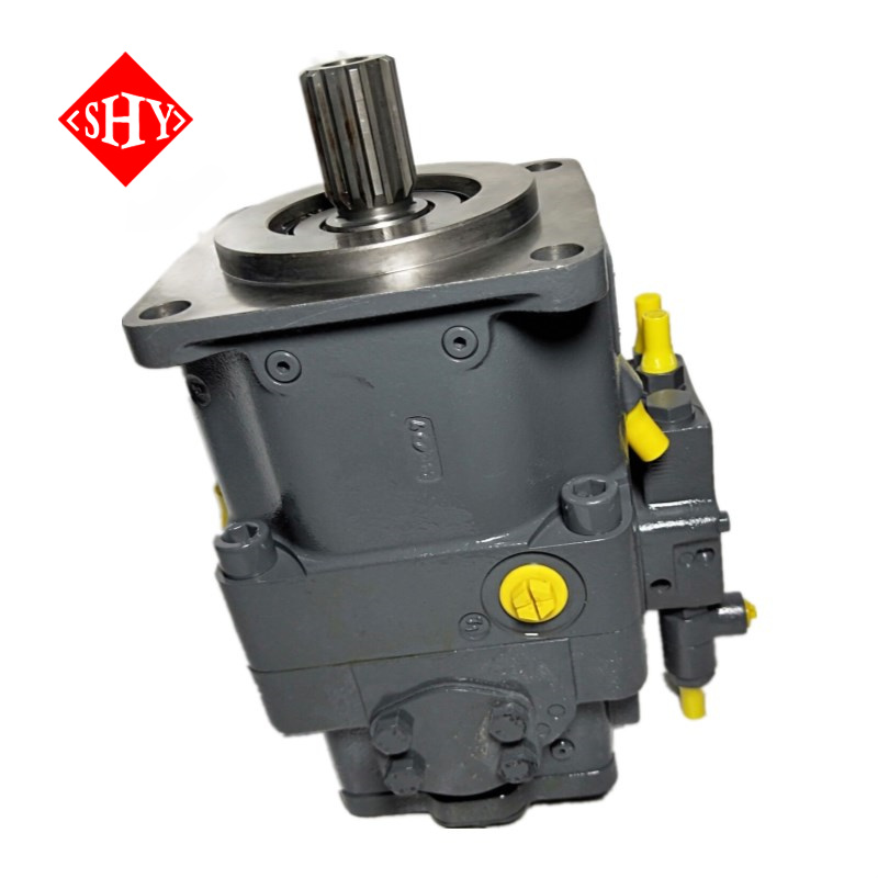
The A11VO A11VLO Hydraulic High Pressure Axial Piston Pump serves as an excellent standard for technical evaluation. Its specific design features, including a robust rotating group and heavy-duty bearings, allow it to handle extreme pressure ratings. The high power-to-weight ratio makes it suitable for compact, mobile, or heavy-duty industrial machinery.
Engineers specify this type of pump when the application demands rapid pressure compensation and high continuous flow. The internal porting and valve plate design are optimized to reduce pressure ripples, resulting in smoother actuator movement and less mechanical shock to the surrounding pipework.
A leading hydraulic pump manufacturer achieves tight internal tolerances to minimize case drain leakage in specialized axial designs. The clearance between the piston and the brass slipper, or the cylinder block and the valve plate, is measured in microns. Precision engineering ensures consistent performance and reduces energy loss.
Inferior manufacturing results in excessive internal bypass. When high-pressure fluid escapes past the pistons into the pump case, it generates massive amounts of heat. A high-quality unit maintains its volumetric efficiency even as fluid temperatures rise, ensuring the machine operates at full speed throughout a heavy production shift.
Calculating required pump displacement requires analyzing actuator speed and cylinder volume requirements. You must determine the maximum flow needed when all cylinders operate simultaneously. Proper sizing prevents system bottlenecks and ensures the pump delivers adequate flow without excessive energy waste.
Oversizing a fixed displacement pump forces excess fluid over the relief valve, turning wasted energy directly into heat. Undersizing the pump results in slow cycle times and operator frustration. You must calculate the exact cubic inches per revolution required and match it to the prime mover's RPM.
Internal leakage, or slippage, increases with pressure and temperature. Evaluating a pump's efficiency curve helps prevent system overheating. As fluid heats up, it thins out, making it easier for it to slip past internal clearances. This creates a destructive cycle where heat causes more slippage, which in turn generates more heat.
Effective thermal management maintains fluid viscosity and protects internal seals from premature degradation. You must integrate properly sized oil coolers and ensure the reservoir has enough capacity to allow the fluid to dwell and release heat before returning to the pump inlet.
The relationship between the hydraulic fluid's properties and the pump's mechanical tolerances is critical. Incorrect fluid viscosity can lead to increased wear, reduced efficiency, and potential cavitation. If the oil is too thick during a cold start, the pump cannot draw it in, causing dry running and immediate metal-to-metal contact.
Always match fluid specifications to the pump manufacturer's recommendations. Consider the ambient operating environment. A machine working in freezing temperatures requires a different multi-viscosity fluid than a power unit sitting next to a blast furnace. Regular oil sampling helps track viscosity breakdown and contamination levels.
When selecting a manufacturer, focus on CNC machining precision, metallurgy of the cylinder blocks, and the quality of internal seals. High material standards ensure the pump can withstand continuous high-pressure operation without catastrophic failure. The hardness of the swashplate and the surface finish of the pistons dictate the unit's lifespan.
Look for manufacturers who utilize advanced heat treatment processes for their rotating groups. The internal components must resist galling and fatigue under rapid pressure spikes. A well-manufactured pump will survive shock loads that would shatter inferior cast components.
Procurement checklists should include ISO certifications, documented testing protocols, warranty structures, and availability of replacement parts. A high-quality hydraulic pump comes with a factory test report proving it met flow and pressure specifications before shipping.
Consider the availability of seal kits and replacement rotating groups. Even the best pumps eventually require rebuilds. Partnering with a manufacturer that provides clear service manuals and readily available parts ensures you can perform maintenance quickly without waiting weeks for proprietary components.
Cavitation and aeration are destructive phenomena that sound like marbles rattling inside the pump housing. Cavitation occurs when restricted inlet flow causes the fluid to boil under vacuum, forming vapor bubbles that collapse violently when exposed to pressure. Aeration happens when outside air gets sucked into the inlet line through a loose fitting or low reservoir level.
Mitigation strategies include:
Sizing the suction line to keep fluid velocity below 4 feet per second.
Eliminating sharp 90-degree elbows in the inlet plumbing.
Maintaining the reservoir fluid level well above the suction strainer.
Installing a breather cap that prevents dirt entry while allowing the tank to breathe.
Fluid contamination remains the leading cause of hydraulic pump failure. Dirt, metal shavings, and water destroy internal clearances. Specify the necessary micron ratings for filtration systems based on the pump type. Piston pumps require much stricter filtration (often 10 microns or less) than gear pumps due to their tight internal tolerances.
Implement a kidney-loop filtration system on large reservoirs to continuously clean the oil independent of the main pump operation. Use desiccant breathers to strip moisture from the air entering the tank. Clean fluid extends the life of the pump exponentially.
Initial start-up requires specific steps to ensure seal integrity and prevent dry running. Never start a new pump dry. Proper commissioning prevents immediate damage and sets the foundation for long-term reliability.
Fill the pump case with clean hydraulic fluid through the highest case drain port.
Leave the discharge line slightly loose to bleed trapped air from the system.
Jog the electric motor in short bursts to verify correct rotation direction.
Run the system at low pressure for 15 minutes to flush out remaining air before applying a full load.
Audit your current system's flow and pressure requirements by installing inline flow meters and pressure transducers to capture real-time operational data.
Consult with a certified fluid power engineer to verify your displacement calculations and ensure the selected architecture matches your duty cycle.
Request detailed performance curves and volumetric efficiency charts from shortlisted manufacturers to validate their claims.
Implement a strict fluid cleanliness program, upgrading return line filters and installing desiccant breathers before installing the new pump.
A: Pumps convert mechanical energy from an engine or electric motor into fluid power by pushing hydraulic oil through a circuit. Motors do the exact reverse, taking that pressurized fluid flow and converting it back into rotational mechanical energy to drive machinery.
A: Overheating usually stems from excessive internal slippage due to worn components, degraded fluid viscosity, or operating the system continuously over the specified pressure relief settings, which forces fluid to dump and generate friction heat.
A: Evaluate their manufacturing tolerances, request factory test reports for their units, ensure they hold relevant ISO certifications, and verify they have a robust support network for replacement parts and technical documentation.
A: Cavitation is caused by restricted inlet flow, excessively thick fluid viscosity, or running the pump drive speed too high. This creates a vacuum that forms vapor bubbles in the oil, which then collapse violently and erode internal metal surfaces.
A: Yes, replacing a fixed gear pump with a variable piston pump improves energy efficiency and reduces heat generation. However, it requires a system redesign, changes to the relief valve setup, and involves a higher initial component cost.
A: The A11VO A11VLO series is engineered for heavy-duty applications, typically handling continuous nominal pressures around 350 bar (5000 PSI) and peak intermittent pressures up to 400 bar (5800 PSI), depending on the specific frame size.


