


Views: 0 Author: Site Editor Publish Time: 2026-08-27 Origin: Site


Industrial hydraulic systems in plastic injection molding, forging, cutting, and heavy engineering machinery demand continuous, high-pressure fluid power with minimal acoustic output. When a primary power unit fails on the factory floor, you need an immediate, exact replacement. Specifying the incorrect pump displacement, housing configuration, or shaft type leads to system cavitation, premature cartridge failure, and costly unplanned downtime. Engineers must precisely match existing system parameters when replacing or upgrading legacy units to avoid modifying existing pipework or motor mounts. Originally developed by Yuken and now a global standard, the PV2R series offers high-performance reliability. This guide provides a rigorous technical breakdown of the PV2R vane pump series, evaluating single and double configurations, decoding complex model numbers, and outlining critical implementation realities to ensure optimal system integration.
Acoustic Efficiency: The PV2R series is engineered specifically for low-noise operation at high pressures, making it the industry standard for indoor manufacturing environments.
Configuration Flexibility: Single pumps (PV2R1, PV2R2) offer precise fixed displacements, while double pumps (PV2R12 through PV2R34) utilize a tandem housing and common shaft to power two independent hydraulic circuits from a single prime mover.
Cartridge Design: The internal cartridge kit design allows for rapid in-field maintenance and displacement modifications without removing the pump housing from the mounting flange.
Specification Precision: Accurate procurement requires decoding full model numbers (e.g., rotation direction, discharge port positioning, installation type, and shaft type) to ensure drop-in compatibility.
Defining a successful pump specification requires aligning several dynamic variables on the machine. You must match the volumetric output to the specific actuator demand to achieve the correct cylinder extension speed. You must maintain fluid velocity within safe operational limits to prevent aeration in the suction line. Furthermore, you must ensure the electric prime mover possesses sufficient horsepower to drive the pump at peak pressure without stalling. A properly specified PV2R vane pump meets these criteria while delivering consistent flow without generating excessive heat in the reservoir.
The internal mechanics of this series rely on a sophisticated intra-vane design. As the rotor turns, centrifugal force and pressurized fluid push the vanes outward against the cam ring. The balanced rotor design is a primary engineering feature that separates this unit from unbalanced gear pumps. High-pressure fluid enters the cartridge from two opposing sides simultaneously. This symmetrical pressure distribution neutralizes radial hydraulic forces acting on the shaft. By eliminating these side loads, the design drastically extends bearing life and ensures high-pressure stability during continuous duty cycles on heavy machinery.
Acoustic performance sets this series apart from standard gear or piston alternatives. The specialized cam profile controls the acceleration and deceleration of the vanes with extreme precision. The cam ring is not a perfect oval; it features specific dwell zones that manage the fluid transition. Optimized port timing reduces sudden pressure pulsations as fluid moves from the suction zone to the discharge zone. This smooth volumetric transition directly translates to lower operational decibel levels. Manufacturing facilities utilizing indoor hydraulic presses benefit significantly from this low-noise architecture, improving workplace safety and compliance with occupational noise exposure limits.
To understand the mechanical advantage, consider the internal fluid routing. The intra-vane setup channels system pressure directly under the vane. This constant outward force ensures the vane tip maintains unbroken contact with the cam ring, even as the cam profile changes shape. This continuous contact prevents internal fluid slip, maintaining high volumetric efficiency even as the system approaches maximum operating pressure.
The PV2R1 frame size represents the foundation of the series. It provides reliable fluid power for low-to-medium flow requirements. Displacement ranges typically span from 6cc to 31cc per revolution. These units operate efficiently at maximum pressures up to 21 MPa (approximately 3000 PSI). Optimal shaft speeds fall between 1200 and 1800 RPM, aligning perfectly with standard four-pole industrial electric motors.
Decoding the model number ensures accurate replacement on the factory floor. Consider the PV2R1-8-F-RAA-40 single vane pump as a primary example. The nomenclature breaks down into specific, actionable data points for the maintenance team:
PV2R1: Denotes the physical frame size of the housing.
8: Indicates a volumetric displacement of 8cc per revolution.
F: Specifies a flange mounting configuration, which bolts directly to the motor bell housing.
R: Dictates clockwise shaft rotation when viewed from the shaft end.
AA: Represents standard port discharge angles, meaning the suction and discharge ports align in a specific orientation relative to the mounting flange.
40: Represents the manufacturer design number, which dictates internal seal and bearing revisions.
Engineers deploy the PV2R1 series in specific operational contexts. Ideal use cases include light-to-medium duty clamping circuits on injection molding machines. They also serve as excellent pilot pressure generators for larger proportional directional control valves. Additionally, these pumps frequently drive auxiliary cooling and filtration circuits in heavy engineering machinery, operating independently from the main hydraulic drive to maintain fluid cleanliness and temperature.
When system actuators demand higher flow rates, you step up to the PV2R2 frame size. This series features increased volumetric capacity and a more robust structural housing to handle higher fluid volumes. The internal cartridge kits are physically larger, requiring a wider cam ring and a longer rotor to displace more fluid per revolution. The shaft diameter also increases to handle the higher torque requirements transmitted from the electric motor.
Selecting the correct displacement dictates system efficiency. When evaluating a PV2R2-26/33/41/47 vane pump, you must calculate the exact flow requirements of the hydraulic cylinders or motors. Choosing between 26cc, 33cc, 41cc, or 47cc depends entirely on the target cylinder extension speed at a given motor RPM. For example, a 47cc pump driven at 1450 RPM delivers a theoretical flow of 68.15 liters per minute. A 26cc unit at the same speed delivers only 37.7 liters per minute. Installing the 47cc unit in a system designed for the 26cc unit will cause excessive fluid velocity, massive pressure drops across the directional valves, and severe heat generation.
The PV2R2 excels in primary power applications. These units provide the main system flow for medium-tonnage hydraulic presses. They are standard equipment on industrial cutting machinery, such as large-scale metal shears and band saws. Leather processing equipment and automated forging lines also rely on the PV2R2 for consistent, high-volume fluid delivery under fluctuating load conditions.
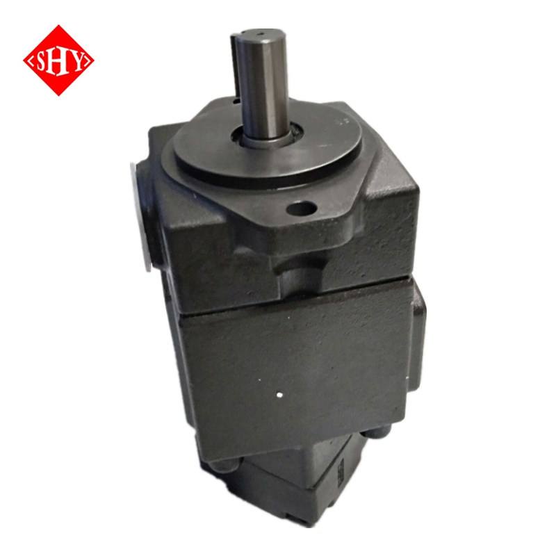
Complex engineering machinery often requires multiple independent hydraulic circuits. Double pumps solve this requirement efficiently. These units combine two single pump cartridges into one tandem housing. A single, continuous shaft drives both the front and rear rotors simultaneously. The front cartridge (shaft end) and the rear cartridge (cover end) draw fluid from a shared suction port in the center of the housing, streamlining the inlet piping.
This tandem configuration offers substantial space-saving benefits. Instead of mounting two separate electric motors and two separate pumps, you utilize one prime mover. This eliminates the need for a second bell housing, a second flexible coupling, and additional mounting brackets. Consolidating the power unit footprint is highly advantageous in mobile engineering machinery and compact factory layouts where floor space is limited.
The common shaft design requires careful torque calculations. The electric motor must provide enough starting torque to overcome the inertia of both rotors simultaneously. Furthermore, the shaft itself must be rated to handle the combined torsional load of both cartridges operating at maximum pressure. If the combined load exceeds the shaft's yield strength, the shaft will shear at the keyway.
Specifying a double pump requires careful attention to dual displacement parameters. Let us decode the PV2R12-14-47-F-REAA-43 double vane pump. The "PV2R12" prefix indicates a combination of a PV2R1 cartridge on the shaft end and a PV2R2 cartridge on the cover end. The "14" signifies a 14cc displacement for the front pump. The "47" signifies a 47cc displacement for the rear pump. The "F" denotes flange mounting. The "REAA" string defines clockwise rotation (R) and specifies the exact angular orientation of the suction port and both discharge ports relative to the mounting flange.
The series expands well beyond the PV2R12. Larger tandem combinations include the PV2R13, PV2R14, PV2R23, PV2R24, and PV2R34. Heavy-duty forging presses and large-tonnage plastic injection machines utilize these massive double pumps. A PV2R34, for example, combines the massive flow capabilities of a frame size 3 and a frame size 4 cartridge, delivering immense fluid power from a single shaft.
Independent discharge ports allow engineers to design highly efficient high-low hydraulic circuits. In a typical press application, the large displacement cartridge (e.g., 47cc) and the small displacement cartridge (e.g., 14cc) combine their flow to rapidly advance the press cylinder. Once the cylinder meets resistance and pressure builds, an unloading valve dumps the large pump's flow back to the tank at near-zero pressure. The small pump continues to supply high pressure to perform the actual pressing or clamping work. This high-low circuit drastically reduces horsepower requirements and minimizes heat generation in the reservoir.
Evaluating pressure capabilities requires distinguishing between continuous and peak ratings. Continuous pressure represents the maximum load the pump can sustain indefinitely without accelerating wear. Peak pressure is the absolute maximum load permitted for brief, intermittent intervals. Exceeding continuous pressure ratings for extended periods causes the fluid film between the vanes and the cam ring to break down, resulting in metal-to-metal contact and rapid cartridge destruction.
Volumetric efficiency measures the actual flow delivered compared to the theoretical flow calculated by displacement and RPM. Internal leakage, known as slip, impacts this efficiency. As system pressure increases, more fluid slips backward across the internal clearances from the high-pressure zone to the low-pressure zone. High-quality PV2R pumps maintain volumetric efficiencies above 90% at rated pressures. To calculate actual flow delivery, you must multiply the theoretical flow by the volumetric efficiency percentage.
For example, if a pump has a theoretical output of 50 liters per minute and operates at 20 MPa, the internal slip might reduce the actual output to 46 liters per minute. You must account for this 4-liter loss when sizing the hydraulic cylinders to ensure they meet the required cycle times.
Physical integration into the hydraulic power unit depends on the installation type. The standard Flange mounting (F) utilizes a standard SAE or metric bolt pattern to attach directly to a motor bell housing. This ensures near-perfect shaft alignment and protects the coupling from external debris. Flange mounting is the preferred method for new OEM equipment designs.
Foot mounting (L) utilizes a heavy cast bracket bolted to the bottom of the pump. The pump and motor sit side-by-side or end-to-end on a shared baseplate, connected by an exposed flexible coupling. Foot mounting is common in legacy retrofits where bell housings are impractical or when dealing with massive electric motors. Space constraints and structural rigidity dictate the selection. Foot-mounted setups require meticulous manual alignment using a dial indicator to prevent shaft fatigue.
Standard PV2R units operate flawlessly with premium anti-wear (AW) mineral-based hydraulic oils. These fluids provide the necessary lubricity to protect the vane tips and cam ring. The optimal kinematic viscosity range during normal operation is typically between 20 and 50 cSt. Maintaining fluid temperature within a strict window ensures the viscosity remains within this optimal band. If the fluid gets too hot, the viscosity drops, internal slip increases, and the pump loses efficiency.
Specialized applications require alternative fluids. Operating with water-glycol, phosphate esters, or synthetic fire-resistant fluids necessitates specific modifications. You must specify Viton (FKM) seals instead of standard Buna-N (Nitrile) seals to prevent chemical degradation. Furthermore, water-based fluids possess lower lubricity and higher specific gravity. Consequently, you must derate the pump's maximum operating pressure and maximum RPM to prevent cavitation and premature wear.
The internal cartridge kit design provides exceptional scalability. The entire pumping mechanism slides out of the housing as a single assembled unit. If a machine requires a slight increase in cycle speed, maintenance personnel can swap a 26cc cartridge for a 33cc cartridge within the same PV2R2 housing.
This interchangeability allows facilities to scale pump output up or down without altering the external steel piping, changing the mounting flange, or replacing the electric motor. This modularity reduces upgrade times from days to hours. It also standardizes the physical footprint of the power unit, simplifying future maintenance procedures.
To execute a cartridge swap on the factory floor, follow this exact procedure:
Isolate the hydraulic power unit and lock out the main electrical disconnect to prevent accidental motor startup.
Close the suction line isolation valve to prevent reservoir drainage.
Remove the four socket head cap screws securing the pump cover to the main housing.
Carefully slide the cover off, exposing the internal cartridge assembly.
Extract the old cartridge kit as a single unit, noting the alignment pin position relative to the housing.
Lubricate the new cartridge O-rings with clean hydraulic fluid.
Insert the new cartridge, ensuring the alignment pin seats perfectly into the housing recess.
Reinstall the cover and torque the cap screws to the manufacturer's specified limit in a cross-pattern.
Frame Size | Displacement Range (cc/rev) | Max Continuous Pressure (MPa) | Max Speed (RPM) | Typical Application |
|---|---|---|---|---|
PV2R1 | 6 to 31 | 21 | 1800 | Pilot circuits, cooling, light clamping |
PV2R2 | 26 to 65 | 21 | 1800 | Main flow for medium presses, cutting |
PV2R3 | 76 to 125 | 21 | 1800 | Heavy forging, large injection molding |
PV2R4 | 136 to 237 | 21 | 1500 | Massive industrial hydraulic power units |
Fluid starvation is the primary cause of catastrophic vane pump failure. Undersized suction lines, excessive elbows, or clogged suction strainers restrict fluid flow to the pump inlet. This restriction drops the inlet pressure below the fluid's vapor pressure, causing dissolved air to expand into bubbles. As these bubbles enter the high-pressure discharge zone, they implode violently. This phenomenon, known as cavitation, blasts microscopic pieces of metal from the cam ring and rotor.
Mitigating cavitation requires strict adherence to fluid velocity limits. You must size the suction line piping to keep fluid velocity below 4 feet per second (1.2 meters per second). To calculate this, use the formula: Velocity = (Flow Rate x 0.3208) / Area of the pipe. Additionally, the reservoir design should maintain positive head pressure at the pump inlet. Mounting the pump below the fluid level in the reservoir guarantees a flooded suction port, eliminating the risk of dry starts and starvation.
Mechanical misalignment destroys pumps rapidly. Angular misalignment occurs when the pump shaft and motor shaft are not perfectly parallel. Parallel misalignment occurs when the shafts are parallel but offset from one another. Both conditions impart severe radial loads on the pump shaft. This causes premature shaft seal failure, resulting in external oil leaks, and accelerates bearing fatigue.
Proper installation requires utilizing high-quality flexible couplings equipped with elastomeric spiders. These couplings accommodate minor thermal expansion and microscopic misalignments. However, they do not excuse poor installation practices. You must adhere to strict Total Indicator Reading (TIR) tolerances using a dial indicator during installation.
Follow these steps for proper foot-mounted alignment:
Mount the dial indicator base to the electric motor shaft.
Position the indicator tip against the outer diameter of the pump coupling half.
Rotate the motor shaft slowly by hand and record the Total Indicator Reading (TIR) for parallel alignment.
Adjust the motor shims until the parallel TIR falls below 0.005 inches.
Reposition the indicator tip against the face of the pump coupling half.
Rotate the shaft again to measure angular misalignment.
Adjust the mounting bolts until the angular TIR is within acceptable tolerances.
Hydraulic fluid acts as both a power transmission medium and a lubricant. Particulate contamination compromises both functions. Dirt, metal shavings, and degraded seal material circulate through the system and enter the pump. These abrasive particles score the rotor slots, causing the vanes to stick. If a vane fails to extend against the cam ring, the pump loses volumetric efficiency and generates massive internal heat.
Implementing rigorous contamination control is non-negotiable on the factory floor. Facilities must maintain ISO 4406 cleanliness standards, typically aiming for an 18/16/13 rating or better for vane pump circuits. Achieving this requires installing high-efficiency 10-micron absolute return line filters. Additionally, reservoirs must feature desiccant breather caps to prevent airborne dust and ambient moisture from entering the hydraulic fluid.
Verify existing pump nameplate data, specifically noting the displacement, rotation direction, and port orientation codes before ordering a replacement.
Measure the existing shaft dimensions with calipers to ensure compatibility with your current flexible coupling.
Inspect the suction line for restrictions and calculate fluid velocity to guarantee it remains below 4 feet per second.
Consult with a hydraulic specialist to confirm seal material compatibility if using any fluid other than standard mineral-based AW hydraulic oil.
A: Most standard PV2R series pumps handle a maximum continuous operating pressure of 21 MPa (approximately 3000 PSI). Operating at peak pressure continuously degrades the fluid film and reduces the lifespan of the internal cartridge. Always verify the specific pressure rating for your exact frame size and displacement on the manufacturer data sheet.
A: Yes. Double pumps feature two separate internal cartridges driven by a common shaft. They utilize separate discharge ports. This configuration allows them to supply pressurized fluid to two entirely independent hydraulic circuits simultaneously. You can also route the flow through specific valving to combine the output for high-low circuit designs.
A: This code specifies a PV2R1 frame size pump with an 8cc per revolution displacement. The "F" indicates a flange mounting style. The "R" denotes clockwise shaft rotation. "AA" specifies the standard orientation of the suction and discharge ports. Finally, "40" represents the manufacturer design series number.
A: Changing rotation requires disassembling the pump and physically reversing the internal cam ring and port plates within the cartridge kit. You must perform this procedure in a clean environment to prevent contamination. We generally recommend ordering the pump with the correct rotation directly from the factory to ensure proper internal alignment and warranty compliance.
A: Cartridge kits are interchangeable only within the same frame size. For example, you can swap a 26cc cartridge for a 33cc cartridge inside a PV2R2 housing. You cannot install a PV2R2 cartridge into a PV2R1 housing due to significant physical size differences in the cam ring and rotor dimensions.
A: A high-pitched whining or rattling noise usually indicates cavitation or aeration. This occurs when restricted suction flow or air enters the inlet line. Check the suction strainer for clogs, ensure the inlet piping meets the correct diameter requirements, and verify all suction line clamps and fittings are completely airtight.


