


Views: 0 Author: Site Editor Publish Time: 2026-09-10 Origin: Site


Incorrectly sizing a hydraulic pump creates compounding operational failures. Over-specifying leads to excessive heat generation, wasted energy, and an unnecessary spatial footprint. Under-specifying results in sluggish actuator response, severe cavitation, and premature mechanical breakdown. Engineers constantly face the bottleneck of balancing precise flow rates and pressure demands against system efficiency constraints. You cannot rely on guesswork or simple catalog lookups to build a reliable fluid power system. A systematic, formula-driven evaluation framework is required. Calculating exact system requirements allows you to map those demands directly to the correct pump architecture. This alignment ensures long-term operational stability, reduces thermal loads, and maximizes the lifespan of your prime mover. We will break down the exact mathematical formulas, architecture comparisons, and implementation strategies needed to size your next pump accurately and rapidly.
Accurate sizing requires calculating both theoretical displacement and actual flow by factoring in specific volumetric efficiency losses.
Selecting between fixed and variable displacement architectures fundamentally dictates system heat generation, energy consumption, and control complexity.
Peak pressure ratings should only be used for transient spikes; continuous operating pressure and duty cycle profiling must dictate the primary sizing baseline.
Mitigating implementation risks—such as inlet suction limits, fluid viscosity mismatches, and shaft alignment—is as critical to pump lifespan as the mechanical sizing itself.
Actuator speed dictates your required flow rate. You must calculate the exact volume of fluid needed to move cylinders or hydraulic motors at target speeds. Flow rate is typically measured in Gallons Per Minute (GPM) or Liters Per Minute (LPM). Once you determine the required flow, you convert it into pump displacement per revolution. Theoretical displacement assumes perfect efficiency, but real-world applications experience internal leakage, known as slip. You must divide your theoretical flow by the pump's volumetric efficiency rating to find the actual required displacement.
Follow this exact sequence to determine your required displacement:
Calculate the total volume of the hydraulic cylinder (Area × Stroke Length).
Divide that volume by the target extension time to find the required flow rate per minute.
Convert the required flow into GPM or LPM.
Use the standard industry formula to find theoretical displacement: Displacement = (GPM × 231) / RPM.
Divide the theoretical displacement by the pump's volumetric efficiency (e.g., 0.90 for a 90% efficient pump) to establish the final sizing requirement.
Pressure determines the amount of work the system can perform. Sizing a pump based on its maximum peak pressure rating for continuous operation guarantees catastrophic component fatigue. Peak pressure ratings exist strictly to handle transient spikes, such as a cylinder hitting a hard stop, a sudden load shift, or a momentary blockage in the line.
Your sizing baseline must rely on continuous operating pressure. This is the sustained pressure required during the majority of the machine's active cycle. Operating a pump continuously at its peak limit destroys internal bearings, blows out shaft seals, and warps internal valve plates. Always leave a 10 to 15 percent safety margin between your system's continuous operating pressure and the pump's maximum rated limit. If your system requires 3000 PSI continuously, select a pump rated for at least 3500 PSI continuous duty.
A time-weighted average load profile is necessary for accurate sizing. You must map out how long the pump operates under high pressure versus low pressure idle times. This duty cycle profiling dictates heat generation and cooling requirements. A system running at maximum pressure for 80 percent of its cycle requires different sizing considerations than one spiking for only 10 percent.
Prime mover speed limits strictly constrain your displacement choices. Standard electric motors run at synchronous speeds, typically 1450 RPM or 1750 RPM. Diesel engines operate across variable RPM bands. If your prime mover is locked at 1450 RPM, you must select a larger displacement pump to achieve the same target flow rate that a smaller pump could deliver at 2500 RPM.
Operational Phase | Duration (Seconds) | Required Flow (GPM) | Required Pressure (PSI) |
|---|---|---|---|
Rapid Advance | 10 | 40 | 500 |
Pressing / Work Stroke | 25 | 15 | 3200 |
Dwell / Hold | 15 | 0 (Leakage only) | 3200 |
Rapid Retract | 10 | 45 | 800 |
The prime mover must possess enough mechanical power to drive the pump under full load. Stalling occurs when the pump demands more torque than the electric motor or diesel engine can supply. You calculate required mechanical input power using this formula: Horsepower (HP) = (GPM × PSI) / (1714 × Overall Efficiency).
Overall efficiency combines both volumetric and mechanical efficiency. If your calculation yields 45 HP, you must select a prime mover rated for at least 50 HP to accommodate start-up surges and mechanical friction. Matching the pump's power curve to the prime mover's continuous rating prevents overheating the electric motor windings or lugging the diesel engine. Never size the motor based on average pressure; you must size it based on the maximum pressure and flow combination the pump will experience simultaneously.
Closed-loop systems route exhaust fluid from the hydraulic motor directly back into the pump inlet. This architecture dominates high-pressure mobile equipment and hydrostatic drives. It provides seamless bidirectional control without requiring large directional valves. Closed-loop circuits demand pumps with high power density and rapid response times.
The A4VG28/71/125 variable hydraulic pump series serves as a benchmark for these applications. Its swashplate design allows for precise, infinitely variable flow control. Closed-loop pumps require an integrated charge pump. The charge pump replenishes fluid lost to internal leakage, maintains positive pressure in the low-pressure loop, and circulates cool fluid through the pump casing to prevent thermal breakdown. Without a properly sized charge pump, a closed-loop system will cavitate and destroy the main rotating group within minutes.
Open-loop circuits draw fluid from a reservoir and return it to the same reservoir after passing through actuators. Industrial presses, excavators, and heavy manufacturing machinery rely heavily on open-loop architectures. Variable displacement piston pumps in open loops excel at matching exact flow demands, significantly reducing energy waste.
Equipment like the A10VSO18/45/140 axial piston pump series illustrates the versatility of open-loop designs. These units utilize advanced compensators to optimize performance. A standard pressure compensator (DR) destrokes the pump to zero flow when a preset pressure is reached, holding pressure without generating excess heat. Flow and load-sensing compensators (DFR) adjust both flow and pressure dynamically based on actuator demand. Proportional electric controls (ED) allow integration with PLCs for highly automated, energy-efficient operations.
Vane pumps offer distinct advantages in environments demanding low acoustic footprints and smooth, pulsation-free flow. They operate efficiently at medium pressures, making them ideal for indoor industrial settings. The sliding vanes adjust to wear over time, maintaining consistent volumetric efficiency longer than standard gear pumps.
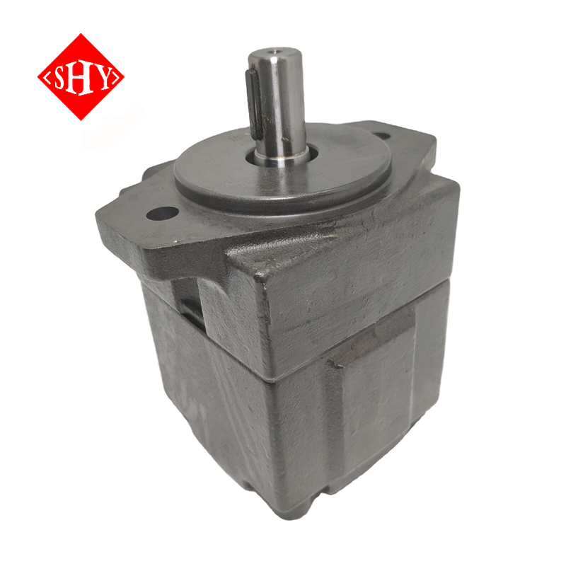
The PV2R1-6/17/31 single vane pump series exemplifies modern cartridge-style designs. Cartridge kits house the rotor, vanes, and cam ring in a single removable unit. This design allows maintenance teams to rebuild the pump in minutes without disconnecting the main housing from the piping. This drastically reduces downtime in critical applications like plastic injection molding machines and industrial presses. When a vane pump fails, you simply swap the cartridge rather than replacing the entire pump assembly.
External and internal gear pumps represent the fixed-displacement baseline for low-to-medium pressure applications. They force fluid between meshing gear teeth and the pump casing. Gear pumps feature simple construction with very few moving parts, making them highly economical and easy to troubleshoot.
While gear pumps exhibit lower volumetric efficiency compared to piston designs, they offer high tolerance for fluid contamination. They are highly reliable in harsh, dirty environments where fine filtration is difficult to maintain. However, their fixed displacement nature means excess flow must be dumped over a relief valve, generating significant heat in continuous-duty applications. You should reserve gear pumps for intermittent duty cycles or systems where budget constraints outweigh long-term energy efficiency.
Theoretical calculations assume a perfect pump. Real-world sizing requires adjusting for volumetric and mechanical losses. Volumetric efficiency drops due to internal leakage (slip) where fluid bypasses the pumping mechanism and returns to the inlet or case drain. Mechanical efficiency drops due to friction between moving parts and fluid turbulence.
Different architectures yield different efficiency ranges. You must factor these percentages into your final calculations to ensure adequate flow and power. Failing to account for a 15% volumetric loss in a gear pump will leave your actuators moving 15% slower than designed.
Pump Architecture | Typical Volumetric Efficiency | Typical Mechanical Efficiency | Primary Application Strength |
|---|---|---|---|
External Gear Pump | 80% - 85% | 85% - 90% | High contamination tolerance, simple circuits, intermittent duty. |
Vane Pump | 85% - 90% | 85% - 92% | Low noise, smooth flow, easy cartridge replacement, indoor industrial. |
Axial Piston Pump | 90% - 95% | 90% - 95% | High pressure, variable flow, maximum energy efficiency, continuous duty. |
Closed-loop piston pumps cannot function without a charge pump. The charge pump draws fluid from the reservoir to keep the closed loop pressurized, preventing cavitation. It also provides the necessary flow to flush hot fluid out of the main pump casing, carrying away heat generated by internal friction.
You must size the charge pump to deliver roughly 10 to 25 percent of the main pump's maximum displacement. High-speed applications or systems with long hose runs require charge pumps sized at the upper end of that spectrum. Failing to size the auxiliary flow correctly leads to rapid overheating and catastrophic failure of the main rotating group. Always verify the charge relief valve setting matches the manufacturer's specifications to maintain adequate loop pressure.
Hydraulic fluid viscosity changes drastically with temperature. Cold fluid is thick and resists flowing into the pump inlet. Hot fluid is thin and increases internal slip, dropping volumetric efficiency. You must map the relationship between your expected operating temperature range and the fluid's viscosity index.
Extreme cold requires larger inlet line sizing to prevent suction starvation. Extreme heat requires tighter internal pump clearances or the addition of external heat exchangers. Always verify that the pump's maximum and minimum viscosity ratings align with your fluid specifications at operating temperatures.
Follow these steps for cold-weather pump operation:
Install a reservoir heater to bring the fluid up to the minimum pour point before starting the prime mover.
Open the pump case drain line to ensure fluid is not congealed inside the housing.
Jog the electric motor or crank the diesel engine briefly to prime the suction line without applying a full load.
Run the system at low idle and zero pressure until the fluid reaches the manufacturer's recommended minimum operating viscosity.
Fixed displacement systems pump a constant volume of fluid per revolution regardless of system demand. Any excess flow must pass over a relief valve. This action shears the fluid and generates massive amounts of heat. Fixed systems require larger reservoirs and heavier heat exchangers to dissipate this thermal load.
Variable displacement systems adjust their output to match exact actuator demand. When the system requires no movement, the pump destrokes to zero flow while maintaining pressure. This eliminates the heat generated by dumping fluid over a relief valve. Variable pumps offer superior energy efficiency and allow for much smaller fluid reservoirs, making them ideal for modern, compact machine designs.
Proper pump sizing directly dictates the electrical or fuel consumption of the prime mover. An oversized fixed displacement pump forces the motor to work harder than necessary, wasting kilowatts of electricity or gallons of diesel. The excess flow generates thermal energy that degrades hydraulic fluid and destroys elastomeric seals.
Implementing a correctly sized load-sensing variable pump drastically reduces this wasted energy. The pump only consumes the exact horsepower required for the immediate task. This precision reduces the thermal load on the system, often eliminating the need for bulky, forced-air heat exchangers. By keeping the fluid cooler, you extend the life of the oil and reduce the frequency of maintenance intervals.
Pump selection heavily impacts workplace acoustics and safety compliance. Hydraulic pumps generate noise through mechanical vibration and fluid pulsation. High decibel levels cause operator fatigue and violate occupational safety standards in enclosed industrial environments.
Gear pumps produce the highest acoustic footprint due to the aggressive meshing of gears and distinct fluid pulsation. Vane pumps operate inherently quieter due to the smooth sweeping motion of the vanes against the cam ring. Specialized piston pumps feature optimized valve plates and pre-compression volumes to mitigate pressure ripples, significantly lowering their decibel output.
Pump Type | Average Noise Level at 3000 PSI (dBA) | Primary Source of Noise |
|---|---|---|
External Gear Pump | 85 - 95 dBA | Gear tooth meshing and high pressure ripple. |
Axial Piston Pump | 75 - 85 dBA | Piston compression and swashplate vibration. |
Vane Pump | 65 - 75 dBA | Minimal. Smooth vane tracking on cam ring. |
Spatial constraints often dictate pump selection in mobile equipment and compact industrial power units. You must evaluate the physical dimensions of the pump housing, the location of the inlet/outlet ports, and the required clearance for maintenance access.
Mounting flanges and shaft couplings must adhere to strict SAE or ISO standards to ensure proper integration with the prime mover. Mismatched flanges require custom adapter plates, which increase the overall length of the pump assembly. Selecting a pump with standard SAE mounting profiles simplifies installation and reduces the overall system footprint. Pay close attention to rear-ported versus side-ported configurations to ensure your hydraulic hoses can route cleanly without exceeding minimum bend radii.
Cavitation destroys pumps from the inside out. It occurs when the pressure at the pump inlet drops below the fluid's vapor pressure, causing vapor bubbles to form. As these bubbles enter the high-pressure side of the pump, they implode violently, blasting microscopic pits into metal surfaces.
Restricted suction lines, clogged suction strainers, high fluid viscosity, and excessive pump speed cause cavitation. You must engineer the inlet line to maintain a proper Net Positive Suction Head (NPSH). Keep suction lines short, wide, and free of sharp bends. Aeration, a similar issue, occurs when air enters the suction line through loose fittings or low reservoir fluid levels. Ensure all inlet connections are completely airtight.
If you suspect cavitation, follow these troubleshooting steps:
Check the reservoir fluid level to ensure the suction line is fully submerged well below the surface.
Inspect the suction strainer inside the tank for debris buildup or sludge.
Verify the suction hose has not collapsed internally due to high vacuum pressure.
Measure the fluid temperature to ensure the oil is not too cold and viscous for the pump to draw efficiently.
Install a vacuum gauge at the pump inlet port; the reading should never exceed the manufacturer's maximum vacuum specification (typically 5 in-Hg).
Improper coupling between the prime mover and the pump shaft guarantees premature failure. Misalignment forces the pump shaft to bend slightly with every revolution. This constant flexing destroys the shaft bearings and causes the front shaft seal to leak fluid.
You must use flexible couplings to absorb minor misalignments. However, flexible couplings do not excuse poor installation practices. Use a dial indicator or laser alignment tool to ensure the shafts are perfectly concentric. Furthermore, standard hydraulic pumps are not designed to handle heavy radial (side) or axial (thrust) loads. If you are driving the pump with a V-belt or gear drive, you must select a pump with specialized heavy-duty front bearings designed to absorb those specific forces.
Contamination is the leading cause of hydraulic system failure. Different pump architectures require distinct ISO 4406 cleanliness codes. Gear pumps can tolerate relatively dirty fluid, often operating fine with an ISO code of 21/19/16.
Piston pumps feature microscopic clearances between the pistons and the cylinder block. They require strict contamination control. You must maintain an ISO cleanliness code of 18/16/13 or better for high-pressure piston pumps. Install high-efficiency absolute filters on the return line and utilize desiccant breathers on the reservoir to prevent airborne moisture and particulate ingress. Never rely solely on a suction strainer to protect a high-performance variable displacement pump.
The initial start-up phase is critical. Starting a dry pump destroys the internal components within seconds. You must manually fill the pump casing with clean hydraulic fluid before turning on the prime mover. This process, known as case flushing, provides immediate lubrication to the bearings and rotating group.
Execute the following steps during initial commissioning:
Remove the highest case drain plug and fill the pump housing completely with pre-filtered hydraulic fluid.
Verify the rotational direction of the prime mover matches the directional arrow stamped on the pump housing.
Leave the pressure line slightly loose or open a bleed valve to allow trapped air to escape.
Jog the electric motor in short bursts to prime the suction line without building pressure.
Once a steady stream of air-free fluid exits the bleed point, tighten the fittings and slowly increase system pressure while monitoring for abnormal noise or vibration.
Compile your machine's time-weighted duty cycle data to establish exact continuous flow and pressure baselines before selecting a pump architecture.
Calculate the required mechanical input power to verify your existing prime mover can handle the selected pump displacement without stalling under full load.
Request specific CAD models and technical datasheets from the manufacturer to validate spatial footprint, port orientations, and flange compatibility.
Consult with a fluid power engineer to finalize your compensator selection and verify your filtration strategy meets the strict ISO cleanliness standards required for your chosen pump.
A: Determine your required flow rate in GPM based on actuator speed. Multiply the GPM by 231, then divide that number by the RPM of your prime mover. Divide the final result by the pump's volumetric efficiency rating to find the actual required displacement in cubic inches per revolution.
A: Volumetric efficiency measures the fluid lost to internal leakage (slip) within the pump. It affects the actual flow output. Mechanical efficiency measures the power lost to physical friction between moving parts and fluid turbulence. It affects the total mechanical input power required to drive the pump.
A: Overheating typically occurs when a fixed displacement pump dumps excess flow over a relief valve. It can also result from operating the pump above its continuous pressure rating, excessive internal slip due to wear, or inadequate reservoir size preventing proper fluid cooling.
A: Yes, upgrading to a variable displacement pump improves energy efficiency and reduces heat generation. However, you must redesign the hydraulic circuit to remove unnecessary relief valves and ensure the new pump's compensator controls align with your system's load demands.
A: A charge pump is a small auxiliary pump integrated into closed-loop systems. It draws fluid from the reservoir to replenish fluid lost to internal leakage, maintains positive pressure to prevent cavitation, and circulates cool fluid through the main pump casing.
A: Cavitation is caused by a pressure drop at the pump inlet, forming vapor bubbles that implode and damage internal components. Prevent it by using properly sized suction lines, keeping suction strainers clean, operating at correct fluid viscosities, and maintaining proper Net Positive Suction Head (NPSH).


