


Views: 0 Author: Site Editor Publish Time: 2026-07-14 Origin: Site


Hydraulic failure immediately impacts operational efficiency on the job site. Operators notice slow cycle times and a severe loss of breakout force when digging into compacted material. Unpredicted machine downtime directly affects project schedules and eats into profit margins. Isolating the root cause of pressure loss remains a difficult challenge for mechanics and fleet managers. You often struggle to determine the exact failure point without tearing the machine apart. The issue might stem from a failing excavator hydraulic pump, a faulty main relief valve, or internal cylinder bypass. Some fleet owners even experience chronic pressure-holding issues from new. This frustrating reality usually results from sub-par component quality or improper initial calibration at the factory. You need a systematic, evidence-based approach to pressure testing. Proper diagnostic procedures eliminate guesswork and ensure operator safety. This guide provides the exact data needed to make informed maintenance decisions. You will learn how to choose between a simple adjustment, a localized rebuild, or investing in a complete replacement unit.
Safety and Baseline Data First: Accurate diagnostics require bringing hydraulic fluid to operating temperature and strictly adhering to safety protocols (e.g., using whip-checks and verifying suction conditions) before attaching any gauges.
Isolation is Key: Testing must systematically isolate the main pump from the control valves and cylinders to prevent misdiagnosing a relief valve issue as a catastrophic pump failure.
Data-Driven Replacement Decisions: Pressure readings that fall significantly below OEM rated specifications—especially when accompanied by knocking or cavitation—indicate severe internal wear, necessitating a high-quality hydraulic pump replacement.
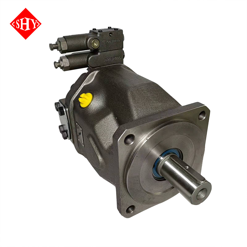
Supplier Vetting: If replacement is required, partnering with a reputable hydraulic pump manufacturer ensures component longevity and exact specification matching (such as upgrading to an A10VSO series hydraulic pump).
Optimal hydraulic performance relies on consistent cycle times and holding pressure under heavy loads. When degradation occurs, the machine exhibits specific physical symptoms that operators feel in the cab. You must define what normal operation looks like for your specific equipment. A healthy system delivers smooth, predictable power to all implements simultaneously. Degraded systems struggle to lift heavy materials or maintain track speed on inclines. Operators often report a spongy feeling in the joystick controls when trying to feather a load. You must investigate these complaints immediately to prevent catastrophic system failure and metal contamination.
Auditory and visual cues provide the first diagnostic clues before you even connect a gauge. Listen closely to the machine during operation under load. Banging or knocking noises often indicate aeration or cavitation inside the housing. These sounds differ completely from normal operational whine. Cavitation sounds like marbles rattling inside a metal blender. This occurs when air bubbles collapse violently under pressure against the valve plate. It destroys internal metal surfaces rapidly and sends shrapnel through the system. Visual cues include jerky cylinder movements or excessive heat radiating from the pump housing. These signs point to fluid dynamics problems rather than simple pressure loss.
You must differentiate main pump failure from secondary component issues to avoid wasting money on the wrong parts. Cylinder drift often mimics pump weakness because fluid bypasses the piston seals. A worn travel motor can also simulate low system flow when tracking across the site. A stuck main relief valve will dump pressure directly back to the tank before it ever reaches the actuators. You must isolate these variables systematically using block-off plates and flow meters. Check the case drain flow to identify internal motor or pump leakage. Isolate the control valves to see if the pressure drop persists. This framework prevents you from replacing expensive components unnecessarily.
Distinguish between long-term component wear and out-of-the-box defects. Normal wear occurs over thousands of operating hours in harsh environments. Internal clearances increase gradually, leading to a slow decline in performance. Conversely, immediate pressure retention issues often stem from poor manufacturing tolerances. Choosing a low-grade unit causes immediate headaches on the job site. You must source components from a certified hydraulic pump manufacturer. Rigorously tested units guarantee proper tolerances and reliable pressure retention from day one.
Field mechanics often misdiagnose pilot pressure issues as main pump failures. The pilot system controls the shifting of the main spools. If pilot pressure drops below 500 PSI, the main spools will not open fully. This restricts flow to the cylinders, making the machine feel weak. Always check the pilot gear pump output before condemning the main variable displacement unit. A simple clogged pilot filter can bring a 30-ton excavator to a crawl. Verify pilot pressure at the designated manifold port using a low-pressure gauge.
Temperature plays a massive role in diagnosing hydraulic faults. A machine that runs perfectly cold but loses power after an hour indicates internal bypass. As hydraulic oil heats up, its viscosity drops. Thin oil easily slips past worn barrel splines and scratched valve plates. Use an infrared thermometer to scan the hydraulic tank, pump housing, and individual cylinders. A localized hot spot indicates fluid forcing its way through a tight restriction or a blown seal. The pump housing should generally run about 20 to 30 degrees hotter than the tank temperature.
Oil sampling provides hard evidence of internal wear before catastrophic failure occurs. Pull a fluid sample from the middle of the reservoir while the oil is warm. Send it to a lab for spectrographic analysis. High levels of copper or brass indicate wearing slipper shoes or cylinder block faces. Elevated iron levels point to bearing or shaft wear. Silicon spikes suggest dirt ingestion through a faulty breather cap or wiper seal. Regular fluid analysis helps you schedule a pump replacement before it explodes and contaminates the entire hydraulic circuit.
High-pressure hydraulic fluid presents extreme dangers to technicians working in the field. Pinhole leaks can inject fluid directly through your skin and into your bloodstream. This causes severe tissue damage and requires immediate surgical intervention. You must mitigate these implementation risks before touching any fittings. Wear heavy-duty safety glasses and protective gloves at all times. Ensure the environmental conditions allow for safe testing on level ground. Clean up any existing oil spills to prevent slip hazards around the machine. Never use your bare hands to check for hydraulic leaks; always use a piece of cardboard or wood.
Accurate testing requires a specific diagnostic tool checklist. Gather these items before starting the procedure to avoid stopping halfway through:
5,000+ PSI liquid-filled pressure gauges to handle pressure spikes without damaging the needle.
System-specific port adapters matching your machine brand (e.g., Cat, Komatsu, or standard BSPP/JIC fittings).
A precise digital timer or stopwatch for cycle validation and drift testing.
Hose whip-checks to secure lines during dead-head testing.
An infrared thermometer to verify fluid operating temperature.
A clean bucket and specialized caps/plugs to cap off open lines immediately.
Securing the test area is a critical safety step that many mechanics overlook. Outline a clear perimeter and keep unauthorized personnel away from the swing radius. Lower all excavator implements flat to the ground so nothing can drop unexpectedly. Turn off the engine and cycle the joysticks repeatedly in all directions. This action relieves residual system pressure trapped in the accumulators. Secure all diagnostic hoses with whip-checks. A blown test hose can whip violently and cause fatal injuries. Double-check every connection before starting the engine.
Verifying system baselines ensures accurate diagnostic data. Check the hydraulic fluid levels in the main tank using the sight glass. Ensure the pump rotation matches the engine output direction if you just installed a new unit. Inspect the suction and inlet conditions for collapsed hoses or loose clamps that could draw in air. You must warm the hydraulic fluid to standard operating temperature. This is usually around 140°F or 60°C. Cold oil has a higher viscosity, which masks internal bypass issues. Testing cold fluid yields inaccurate pressure readings and false diagnostics.
Inspect the hydraulic tank breather cap before running any tests. A clogged breather creates a vacuum inside the reservoir as fluid levels fluctuate. This vacuum starves the pump inlet, leading to severe cavitation. Replace the breather element if it looks dirty or hasn't been changed in the last 1,000 hours. Also, verify that the suction strainer inside the tank is clean. A restricted suction strainer will destroy a new pump within minutes of startup.
Check the condition of the hydraulic oil itself. Pull the dipstick or look at the sight glass. Milky white oil indicates water contamination. Water destroys the lubricity of the oil and causes rapid rust formation on internal steel parts. Dark, burnt-smelling oil indicates severe overheating. If the oil is degraded, you must drain the tank, flush the system, and refill it with fresh fluid before performing any pressure tests. Testing with bad oil gives you bad data.
Ensure the engine is running at the correct RPM. Hydraulic pumps are driven directly by the engine flywheel. If the engine bogs down under load or fails to reach high idle, the pump cannot produce its rated flow. Use a phototachometer to verify engine RPM matches the specification in the service manual. Fix any fuel delivery or turbocharger issues before blaming the hydraulic system for slow cycle times.
Physical testing follows standardized, repeatable steps applicable to most heavy equipment. You must break down the process into manageable solution categories. Start with visual inspections, move to baseline pressure checks, and finish with flow validation. This structured approach prevents missed steps. It ensures you capture all necessary data for an accurate diagnosis. Always refer to your specific machine's service manual for exact pressure specifications and port locations.
Locating the correct pressure test ports is your first physical task. You will find test ports on the hydraulic pump housing. These are critical for isolated pump output checks. Testing here bypasses the main control valve. Contrast this with check points located on the loader valve block. These ports sit near the main relief valve. Testing at the valve block evaluates the entire circuit's pressure-holding capability. Knowing the difference helps you isolate the exact failure point.
Connecting diagnostic equipment requires cleanliness and precision. Remove the protective caps from the designated test ports. Wipe the area thoroughly with a clean rag and brake cleaner. Dirt or contaminants entering the system will destroy sensitive internal components. Attach the appropriate adapters securely. Thread the liquid-filled gauges onto the adapters. Tighten them with a wrench, but avoid over-torquing and stripping the threads. Route the gauge hoses safely away from moving engine parts, exhaust manifolds, or cooling fans.
Running the stall test captures the maximum operating pressure. Start the engine and set the throttle to high idle. Safely dead-head a specific hydraulic function. You can fully extend the bucket cylinder or lock the track travel with a heavy pin. Hold the joystick in this position for a few seconds. This forces the system fluid over the main relief valve. Read the maximum pressure displayed on your gauge. Release the joystick immediately to prevent excessive heat buildup in the hydraulic oil.
Quantifying flow requires measuring travel cycles and cylinder drift. Use your digital timer to measure travel cycle speeds. Mark a set distance on flat ground, usually about 20 meters. Time how long the excavator takes to travel that distance in both high and low speed modes. Next, measure cylinder drift rates. Raise a loaded bucket and turn off the machine. Measure how far the cylinder rod extends or retracts over five minutes using a tape measure. Cross-reference these times and physical measurements against OEM specifications. This mathematically isolates internal bypass from pump volumetric inefficiency.
Position the machine on level ground and lower the bucket.
Relieve all tank pressure by pressing the breather button.
Install the 5,000 PSI gauge on the front pump delivery port.
Start the engine and warm the hydraulic oil to 140°F.
Select the heavy lift mode on the monitor panel.
Stall the bucket curl function and record the peak pressure.
Repeat the stall test for the boom up and stick out functions.
Compare the recorded pressures against the factory manual.
Testing the negative control pressure is also necessary on many modern excavators. Negative control systems use a pressure signal from the center bypass gallery to destroke the pump when the joysticks are in neutral. Install a low-pressure gauge (usually 0-600 PSI) on the negative control port. When the joysticks are neutral, pressure should be high (around 400-500 PSI), keeping the pump destroked. When you move a joystick, this pressure should drop to near zero, allowing the pump to upstroke and deliver flow. If the negative control pressure remains high during operation, the pump will not produce flow.
Always test both pumps on a dual-pump system. Most excavators use two main pumps bolted together in tandem. One pump typically supplies the right track, boom, and bucket. The other supplies the left track, stick, and swing. If the machine tracks to one side, it often indicates that one pump is weaker than the other. Swap the high-pressure delivery hoses between the front and rear pumps. If the tracking issue moves to the other side, you have confirmed a weak pump. If the issue stays on the same side, the problem lies in the control valve or the travel motor.
Interpreting the gauge readings against OEM specifications provides a clear evaluation framework. You must compare your recorded data directly to the factory manual. Small deviations might require simple adjustments to a set screw. Massive pressure drops indicate severe mechanical failure inside the rotating group. You must analyze the data objectively. Do not guess or assume the condition of internal parts based on age alone. Let the pressure and flow numbers dictate your next maintenance steps.
If the pressure is uniformly low across all functions, consider Scenario A. This usually indicates a weak or contaminated main relief valve. The valve might have a broken spring or debris holding the poppet open. Locate the relief valve adjustment screw on the main control block. Loosen the locknut and turn the screw clockwise slightly. Run the stall test again. If the pressure recovers to OEM specs, the valve was simply out of adjustment. If it fails to rise, the valve requires replacement.
Scenario B involves pressure that fluctuates, drops as temperature rises, or fails to build entirely. This indicates severe internal bypass. As fluid heats up, it thins out. Thin fluid easily escapes past worn internal clearances. This points directly to typical failure points within a piston pump. You will likely find scored barrel faces or worn valve plates. Loose piston shoes also permit massive internal leakage. These conditions prevent the unit from building or holding high pressure.
Symptom Observed | Diagnostic Reading | Probable Root Cause | Recommended Action |
|---|---|---|---|
Uniformly low pressure on all functions | Gauge reads 1000+ PSI below spec | Main relief valve stuck or out of adjustment | Adjust relief valve; clean or replace if no change |
Pressure drops significantly when fluid is hot | Normal cold, low when hot | Internal wear in the main pump assembly | Inspect case drain flow; plan for pump replacement |
Loud knocking or rattling noise | Fluctuating gauge needle | Cavitation or severe aeration | Check suction lines; inspect for internal metal damage |
Single function lacks power | Main pressure normal, port pressure low | Leaking cylinder seals or faulty port relief | Isolate and rebuild specific cylinder or port valve |
Machine tracks to one side | One pump reads 500 PSI lower than the other | Uneven wear in tandem pump setup | Swap delivery hoses to verify; replace weak pump |
Engine bogs down and stalls | Pressure spikes above relief setting | Regulator stuck in maximum displacement | Inspect pump regulator and proportional solenoid |
Overall value influencing factors dictate your final repair decision. You must weigh downtime against long-term reliability. A localized rebuild requires specialty labor and often carries a short warranty. If internal hard parts are heavily scored, a rebuild becomes risky because metal shavings hide in tiny galleries. Installing a brand new, factory-tested high-quality hydraulic pump guarantees immediate uptime. It eliminates the risk of residual contamination causing repeat failures. This approach ensures maximum reliability for heavy-duty earthmoving operations.
Measuring case drain flow provides the final piece of the diagnostic puzzle. The case drain line carries internal leakage back to the tank. Disconnect the case drain hose from the pump and route it into a clean five-gallon bucket. Run the engine at high idle and stall a function for exactly one minute. Measure the volume of oil in the bucket. Compare this volume to the OEM allowable leakage specification. If the bucket fills up rapidly, the internal clearances are completely worn out. The pump must be replaced immediately.
Consider the age and overall condition of the machine before deciding on a repair path. If the excavator has 15,000 hours and the undercarriage is shot, a cheap rebuild might get you through the rest of the season. However, if the machine is a frontline production unit loading trucks every day, you cannot afford unexpected downtime. A new replacement unit provides peace of mind. It ensures the machine hits its production targets without constant mechanic intervention.
When a replacement is the only viable option, scalability and compliance matter. You need a unit that matches your machine's exact performance requirements. Do not settle for unverified aftermarket clones built in unregulated factories. These units often lack proper heat treatment on internal components. They fail quickly under continuous heavy loads. Guide your procurement process by focusing on verified manufacturing standards. A reliable replacement restores your excavator to original factory performance levels.
Evaluating a supplier requires strict selection criteria. Look for ISO 9001 certification and cleanroom assembly standards. Clean assembly prevents microscopic debris from entering the unit during production. Demand 100% end-of-line dynamic testing under load. The factory must verify pressure and flow curves before shipping the unit. Comprehensive warranty coverage is non-negotiable. You also need readily accessible technical support to assist with installation and initial startup procedures.
Application matching ensures the new unit integrates seamlessly with your machine. You must match technical specifications to the exact excavator model. Focus heavily on displacement volume per revolution. Verify the mounting flanges and shaft splines match your engine coupling perfectly. Confirm the control configurations align with your system. You must match load-sensing, constant horsepower, or pressure cutoff controls precisely. Incorrect controls will cause the machine to stall or operate erratically.
Upgrading your system often involves selecting industry-standard designs. The A10VSO series hydraulic pump represents a benchmark in variable displacement technology. Its advanced load-sensing capabilities optimize efficiency. It only delivers the exact flow required by the operator's joystick input. This reduces parasitic engine load and saves fuel. Integrating this type of advanced hydraulic pump maximizes performance in modern excavator circuits.
Always flush the entire hydraulic system before installing a new pump. If the old pump failed catastrophically, it sent metal shavings through the lines, valves, and cylinders. Simply bolting on a new pump without flushing will destroy the new unit within hours. Use a dedicated kidney loop filtration cart to clean the oil. Replace all return and pilot filters. Clean out the hydraulic tank manually with lint-free rags. This extra effort protects your investment.
Proper priming is critical during installation. Never start the engine with a dry pump housing. Remove the uppermost case drain fitting and fill the pump housing completely with clean hydraulic oil. Rotate the pump shaft by hand a few times to ensure the oil coats the bearings and rotating group. Leave the engine stop solenoid disconnected and crank the engine for 15 seconds to build pilot pressure. Reconnect the solenoid, start the engine at low idle, and let it run for ten minutes without operating any functions to bleed trapped air.
Routine pressure testing remains the only definitive way to diagnose underperformance on your heavy equipment. It prevents catastrophic system contamination caused by a disintegrating pump. Guessing leads to unnecessary parts replacement and extended downtime. By following a systematic testing procedure, you isolate the exact point of failure. This data-driven approach protects your equipment investment and ensures operator safety.
Your decision matrix is straightforward. If pressure cannot be restored via relief valve adjustment, internal wear is confirmed. When case drain flow exceeds specifications, the internal clearances are gone. In these scenarios, complete replacement provides the most reliable route forward. It restores full breakout force and cycle speed immediately.
Take these actionable next steps to resolve your hydraulic issues:
Record your current pressure readings and fluid temperatures accurately in a maintenance log.
Locate your machine's exact serial number and the data tag on the original pump housing.
Check the case drain filter for any signs of brass or steel metal flakes.
Contact a specialized manufacturer for a consultation or quote on a certified replacement unit.
Schedule a complete system flush and filter change prior to installing the new component.
A: Most standard excavators operate within a main relief pressure range of 4,000 to 5,500 PSI (275 to 380 bar). However, you must always check your specific OEM manual. Different machine sizes and models have unique pressure settings for travel, swing, and implement circuits.
A: Adjust the main relief valve slightly while monitoring the gauge. If the pressure rises and holds, the valve was out of adjustment. If the pump cannot build pressure regardless of the valve setting, or if case drain flow is excessive, the pump is failing internally.
A: As hydraulic fluid heats up, its viscosity decreases. This thermal thinning allows the fluid to easily slip past worn internal components like piston shoes and valve plates. A worn pump will perform adequately when cold but bypass heavily once the oil reaches operating temperature.
A: No. Testing without a proper liquid-filled gauge is extremely dangerous and provides zero diagnostic value. You cannot feel or guess hydraulic pressure accurately. Attempting to do so risks severe injury from high-pressure injection and leads to incorrect maintenance decisions.
A: You should test hydraulic pressure at major preventative maintenance intervals, typically every 2,000 operating hours. You must also perform a test immediately if operators report slow cycle times, weak breakout force, or abnormal noises coming from the hydraulic system.
A: Cavitation produces a distinct, loud knocking or rattling noise, often described as sounding like marbles in a metal blender. This destructive sound differs completely from the smooth, high-pitched whine of a healthy pump operating under normal load.
A: A new pump may fail if the system was not flushed properly, leading to immediate contamination. Other causes include an incorrectly set main relief valve, improper initial priming, or installing a low-quality unit from an unverified manufacturer instead of a rigorously tested component.


