


Views: 0 Author: Site Editor Publish Time: 2026-08-23 Origin: Site


Open-circuit hydrostatic drives demand precise flow proportionality. Fixed displacement systems waste power by dumping excess flow over a relief valve. This generates massive heat. A variable displacement piston unit solves this by adjusting output to match exact load requirements. Specifying an incompatible displacement size, incorrect control mechanism, or misunderstanding series designations leads to thermal inefficiency. You will face cavitation, premature rotary group failure, and costly machine downtime. We evaluate the A10VSO series below. We compare displacement sizes, control configurations, and series variations like Series 31. You will learn lifecycle realities to ensure accurate specification for industrial and mobile applications.
Displacement Range: The series scales from 18cc to 180cc per revolution, accommodating a wide spectrum of flow requirements while maintaining a standardized 280 bar nominal pressure rating.
Control Versatility: Selection hinges on the control compensator; options range from standard pressure control (DR) to complex pressure, flow, and power control (DFLR).
Holistic Performance: While marketed as a "whisper pump" for low noise, the true value lies in how this optimized acoustic profile correlates directly with greater volumetric efficiency, reliability, and application flexibility.
Lifecycle Management: Long-term reliability is heavily dependent on strict fluid cleanliness (ISO 4406 standards), proper transport and commissioning procedures, and adherence to OEM teardown and inspection protocols.
The foundation of this unit is an axial piston rotary group utilizing a swashplate design engineered for open-circuit hydrostatic drives. Inside the housing, a cylinder block rotates with the input shaft. Pistons housed within this block press against a stationary swashplate via brass slipper pads. Because the swashplate sits at an angle, the pistons reciprocate in and out of their bores as the cylinder block turns. This mechanical reciprocating action draws hydraulic fluid in through the suction port and forces it out through the pressure port.
Drive speed and displacement dictate the total flow output. Adjusting the swashplate angle allows for continuous flow variation. When the swashplate is perfectly vertical at zero degrees, the pistons do not stroke. The pump produces zero flow despite the shaft spinning. As the control compensator increases the swashplate angle, the piston stroke lengthens, proportionally increasing the volumetric output. This dynamic adjustment makes the A10VSO hydraulic pump highly efficient. It only pumps the exact volume of fluid the circuit demands at any given millisecond.
Operational baselines are strictly defined to ensure structural integrity. The unit carries a 280 bar nominal continuous pressure rating. This represents the maximum pressure the pump can sustain indefinitely without accelerating wear on the internal trunnion bearings or valve plate. It also features a 350 bar peak pressure limit. This peak rating accommodates brief pressure spikes during sudden load shifts or actuator bottoming. Continuous operation at 350 bar will lead to rapid fatigue failure.
Parameter | Specification Limit | Field Consequence if Exceeded |
|---|---|---|
Nominal Pressure | 280 bar (4000 psi) | Accelerated trunnion bearing wear. |
Peak Pressure | 350 bar (5100 psi) | Catastrophic housing or shaft failure. |
Max Case Drain Pressure | 0.5 bar above inlet | Main shaft seal blowout and external leakage. |
Fluid Temperature Range | -25°C to +90°C | Loss of fluid viscosity, resulting in metal-to-metal contact. |
Series designations indicate generational improvements and regional standardizations. Series 31 represents a widely adopted global standard for industrial applications. Newer iterations like Series 32 or 52 feature modified housing castings or updated bearing configurations for specific duty cycles. Regional variants exist. The (A)A10VSO designation denotes Americas-specific configurations. These utilize SAE mounting flanges like SAE B or SAE C and UNC/UNF port threads instead of the metric ISO or DIN standards found on European models. Specifying the correct series and regional variant prevents mechanical integration failures on the assembly floor.
Industry literature frequently refers to this unit as a whisper pump. This acoustic claim stems from an optimized port plate design. The timing grooves on the valve plate are machined to gradually decompress the fluid inside the piston bore before it transitions to the low-pressure suction zone. This controlled pressure release minimizes fluid shockwaves, directly reducing airborne noise. Actual decibel output remains highly dependent on external factors. High RPMs, incorrect fluid viscosity, and rigid structural mounting without vibration dampening will negate the acoustic benefits of the internal port plate design.
Lower-displacement models are engineered for precise control in environments where massive flow is unnecessary, but rapid response is mandatory. You will evaluate these sizes for stationary industrial applications, machine tools, plastic injection molding pilot circuits, and compact power units. These applications demand continuous operation, low heat generation, and absolute reliability within a confined physical space.
Performance metrics scale linearly with the displacement size. At a standard industrial electric motor speed of 1500 RPM, the flow rates are predictable. When driven by a combustion engine at higher speeds like 2500 RPM, these outputs increase proportionally, provided the inlet suction line is adequately sized to prevent cavitation.
Displacement Size | Theoretical Flow at 1500 RPM | Theoretical Flow at 1800 RPM | Typical Application |
|---|---|---|---|
Size 18 | 27 L/min | 32.4 L/min | Pilot circuits, small clamping fixtures |
Size 28 | 42 L/min | 50.4 L/min | Machine tool feeds, filtration carts |
Size 45 | 67.5 L/min | 81 L/min | Medium industrial power units |
The physical footprint of the A10VSO18/28/45 axial piston pump offers significant spatial advantages. In space-constrained environments like automated machining centers or mobile lifting platforms, the compact housing allows for tighter packaging of the hydraulic power unit. The smaller casing requires less fluid volume to fill the case drain, simplifying reservoir design and cooling requirements.
A primary evaluation dimension for these smaller units is the relationship between physical mass and operational outcomes. The lower rotational inertia of smaller rotary groups translates directly to faster compensator response times. When a machine tool suddenly demands flow to clamp a part, the smaller swashplate and lighter pistons transition from zero stroke to full stroke in a fraction of a second. This rapid response minimizes pressure drops in highly cyclical machine operations, ensuring consistent actuator speed and improving overall machine cycle times.
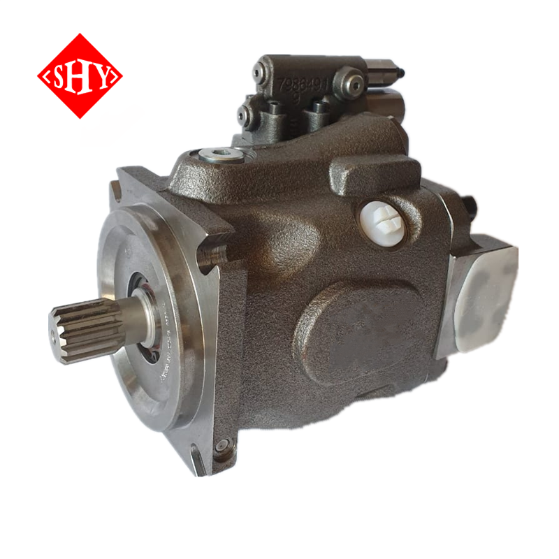
When the application shifts to heavy material handling or massive force generation, larger displacement models become necessary. Sizes 71, 100, and 140 are deployed in demanding environments like excavators, forestry equipment, large-scale metal forming presses, and marine winch systems. These machines require high volumetric output to move large cylinders or drive heavy hydraulic motors quickly.
Managing high volumetric output while maintaining the 280 bar continuous pressure rating introduces specific high-flow dynamics challenges. At these sizes, the fluid velocity entering the suction port is immense. If the inlet line is too restrictive, or if the fluid is too cold and viscous, the pump will cavitate. Cavitation tears metal from the valve plate. The heat generated by internal leakage at 280 bar requires robust case drain plumbing and dedicated hydraulic oil coolers to maintain fluid viscosity.
A major structural advantage of these larger models is their through-drive capabilities. The heavy-duty housing and reinforced input shaft of a A10VSO71/100/140 280 bar excavator pump can accommodate a rear mounting pad and spline. This allows you to mount secondary pumps directly to the rear of the primary pump. You can attach a fixed displacement gear pump for a cooling circuit or another variable piston pump for a separate implement circuit. This enables multi-circuit systems from a single prime mover, eliminating the need for complex splitter gearboxes.
When designing a high-flow system, engineers evaluate scalability. You must decide when to scale up to a single size 140 or 180 versus utilizing two smaller pumps in tandem. A single large pump requires less mounting space and fewer inlet connections. Two smaller pumps in tandem offer redundancy. If one fails, the machine can limp to a maintenance bay. Two smaller pumps can be controlled independently, allowing for complex multi-function operations on mobile equipment without relying on pressure-compensating directional valves.
The mechanical pump is only as effective as its control system. The rotary group simply moves fluid. The compensator dictates when and how much fluid moves. Selecting the wrong compensator leads to system overheating, sluggish actuator response, and wasted horsepower. Understanding the specific mechanics of each control type is non-negotiable for system designers.
The DR control is the baseline pressure compensator. It maintains a set system pressure by destroking the pump when that pressure is met. If you set the DR compensator to 200 bar, the pump stays at maximum displacement until the system resistance reaches 200 bar. At that exact moment, the compensator spool shifts, sending high-pressure fluid to the control piston. The control piston pushes the swashplate back toward zero degrees. The pump then only produces enough flow to maintain 200 bar against internal system leakage. This is ideal for clamping circuits or constant-pressure networks.
The DFR control introduces load-sensing capabilities. This compensator features two spools. One acts as the pressure limiter, while the other senses the actual pressure required by the actuator via a load-sense line. The pump matches flow to the actuator's demand regardless of load variations. If a cylinder only needs 50 bar to move a light load, the DFR control adjusts the swashplate to provide the exact flow requested by the directional valve at 50 bar, plus a small margin called the standby pressure. This drastically reduces heat generation compared to a DR control dumping excess flow over a relief valve.
The DFLR control represents the highest level of mechanical control. It analyzes the mechanics of torque limiting to prevent prime mover stalling. Diesel engines and electric motors have maximum horsepower limits. If a pump operates at maximum flow and maximum pressure simultaneously, it will stall the engine. The DFLR control prevents this by automatically reducing displacement as pressure rises, keeping the horsepower draw constant.
During power shifts, a mechanical linkage inside the control assembly tracks the swashplate angle.
The linkage adjusts the spring tension on the control spool based on the current displacement.
As system pressure spikes, the spool shifts to send fluid to the control piston.
The pump destrokes along a hyperbolic curve, sacrificing speed for force.
The prime mover continues running smoothly without exceeding its torque capacity.
While the A10VSO dominates the industrial and heavy mobile sectors, system designers frequently encounter the A10VNO series during procurement. Clarifying the technical differences between the standard A10VSO and the A10VNO series is required for cost-effective circuit design. Both utilize axial piston swashplate technology, but they are engineered for slightly different operational environments.
The A10VNO series is optimized for specific commercial vehicle applications. You will see a A10VNO28/45/63/85 variable piston pump specified for power take-off drives on trucks, municipal vehicles, and agricultural implements. The primary distinction lies in the mounting flange requirements and housing materials. The A10VNO is designed to bolt directly to commercial vehicle transmissions, featuring specific splines and compact rear housings to clear truck chassis components.
Application overlap occurs frequently. Scenarios where an A10VNO might be specified instead of an A10VSO include cost-optimized circuits where the absolute peak pressure tolerance of the VSO is not required. If a municipal salt spreader only requires 210 bar of continuous pressure, the A10VNO provides the necessary variable displacement functionality without over-engineering the system.
Feature | A10VSO Series | A10VNO Series |
|---|---|---|
Primary Market | Industrial & Heavy Mobile | Commercial Vehicles & PTO |
Peak Pressure Rating | 350 bar | Typically lower (varies by size) |
Mounting Standards | ISO, DIN, SAE | Specific commercial vehicle PTO flanges |
Housing Profile | Standard heavy-duty cast iron | Compact rear profile for chassis clearance |
Procuring the correct pump is only the first step. Improper installation and poor maintenance will destroy a brand-new unit within hours. Transport and handling require strict adherence to safety protocols. Safe lifting practices for heavier units demand the use of designated lifting eyes and nylon slings. Never lift the pump by the control compensator or the input shaft. Pre-installation storage requirements dictate that the pump remains filled with anti-corrosion fluid and sealed until the moment it is bolted to the bell housing to prevent internal rust.
Installation constraints dictate system layout. Critical mounting orientations must be observed. While horizontal mounting is standard, vertical mounting requires specific internal modifications and precise case drain routing. The case drain line must always be routed from the highest available port on the pump housing directly back to the reservoir, terminating below the fluid level. This ensures the housing remains completely full of oil for lubrication and cooling. It prevents housing over-pressurization which blows out the main shaft seal.
Fluid cleanliness and filtration are the most critical factors in pump longevity. The tight tolerances between the pistons and their bores are highly susceptible to contamination. Strict requirement for fluid cleanliness must be maintained. Abrasive particles will score the brass slipper pads and the valve plate, causing internal leakage, severe efficiency loss, and eventual catastrophic failure.
Before bumping the electric motor or cranking the diesel engine, manually fill the pump case with filtered hydraulic fluid.
Crack the highest case drain fitting to bleed trapped air until solid fluid weeps out.
Verify the rotation direction against the pump's data tag. Running a directional pump backward will result in immediate dry-running, destroying the rotary group in seconds.
Start the prime mover at idle speed and allow the pump to circulate fluid at zero pressure for several minutes.
Gradually introduce load and verify the compensator responds correctly using a calibrated pressure gauge.
Over the lifecycle of the machine, teardown, inspection, and reassembly will become necessary. Repair manual protocols outline the critical phases of disassembling the control assembly first, followed by removing the tailstock. Inspecting the rotary group involves checking the pistons for scoring, measuring the slipper pad thickness, and examining the valve plate for smearing or cavitation pitting. Ensuring safe reassembly requires precise torque specifications on all housing bolts and verifying the swashplate moves freely before reinstalling the control block.
Symptom | Potential Cause | Required Action |
|---|---|---|
Fails to build pressure | Sticking compensator spool due to contamination | Remove, clean, and inspect control block spools. |
Excessive heat generation | High internal leakage bypassing to case drain | Measure case drain flow; rebuild rotary group if excessive. |
High-pitched whining noise | Inlet restriction causing cavitation | Inspect suction hose for collapse; clean inlet strainer. |
External shaft seal leak | Blocked or incorrectly routed case drain line | Verify case drain routing to reservoir; replace shaft seal. |
To finalize your system design and ensure long-term reliability, execute the following steps:
Calculate exact volumetric efficiency requirements based on actuator speed and load profiles before selecting a displacement size.
Verify control compatibility by matching the compensator type against the prime mover's horsepower limits.
Establish a customized filtration strategy to meet or exceed ISO 4406 20/18/15 standards prior to initial commissioning.
Route all case drain lines directly to the highest housing port to guarantee internal lubrication and prevent shaft seal blowout.
A: The A10VSO is designed specifically for stationary industrial applications, featuring mounting flanges and port threads suited for factory environments. The A10VO is optimized for mobile applications, utilizing mounting configurations standard to commercial vehicles and heavy machinery. Internally, the rotary groups are nearly identical.
A: No. The A10VSO is engineered exclusively for open-circuit hydrostatic drives. It draws fluid from a reservoir and pumps it to directional valves. Closed-circuit systems require pumps with integrated charge pumps and specific high-pressure relief valves designed to loop fluid directly back from the motor.
A: Series 31 denotes a specific generation of the pump design, indicating internal component dimensions and housing style. The (A)A10VSO variant signifies an Americas-specific version of that series, which utilizes SAE mounting flanges and UNC/UNF threaded ports instead of metric ISO/DIN standards.
A: Adjustments are made via the set screw on the control block. Loosen the lock nut, then turn the set screw clockwise to increase the pressure setting or counter-clockwise to decrease it. Always use a calibrated pressure gauge in the system to verify the exact setting before tightening the lock nut.
A: The maximum continuous case pressure is typically 0.5 bar above inlet pressure, with absolute peaks not exceeding 2 bar. Exceeding this limit will cause the main shaft seal to blow out, resulting in massive external fluid leaks and loss of internal lubrication.
A: A high-pitched whine usually indicates cavitation. This occurs when the pump cannot draw enough fluid, creating a vacuum that forms and collapses vapor bubbles. Check for a restricted suction line, a clogged inlet strainer, or fluid that is too cold and viscous.


